MF1A TRANSFER / 4WD / AWD TRANSFER ASSEMBLY INSPECTION
PROCEDURE

 1.INSPECT PRELOAD
Inspect Driven Pinion Preload:
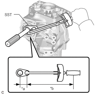
| *a | Length of SST
50 mm (1.97 in.) |
| *b | Length of Torque Wrench
130 mm (5.12 in.) |
Using SST and a torque wrench, measure the preload of the backlash between the driven pinion and ring gear.
- SST
- 09326-20011
| Item | Preload |
|---|---|
| without SST | 0.5 to 0.9 N*m (6 to 9 kgf*cm, 5 to 7 in.*lbf) |
| with SST | 0.3 to 0.6 N*m (4 to 6 kgf*cm, 3 to 5 in.*lbf) |
- NOTICE:
- ·
The "with SST" torque value is effective when using SST with a fulcrum length of 50 mm (1.97 in.).
·The "with SST" torque value is effective when using a torque wrench with a fulcrum length of 130 mm (5.12 in.).
Click hereGeneral>INTRODUCTION>REPAIR INSTRUCTION>PRECAUTION
·The "with SST" torque value is effective when SST is parallel to the torque wrench.
Inspect Total Preload:
Using SST and a torque wrench, measure the total preload.
- SST
- 09326-20011
| Item | Total Preload |
|---|---|
| without SST | 0.4 to 0.5 N*m (4.1 to 5.0 kgf*cm, 3.6 to 4.4 in.*lbf) + Driven pinion preload |
| with SST | 0.25 to 0.38 N*m (2.6 to 3.8 kgf*cm, 2.3 to 3.3 in.*lbf) + Driven pinion preload |
- NOTICE:
- ·
The "with SST" torque value is effective when using SST with a fulcrum length of 50 mm (1.97 in.).
·The "with SST" torque value is effective when using a torque wrench with a fulcrum length of 130 mm (5.12 in.).
Click hereGeneral>INTRODUCTION>REPAIR INSTRUCTION>PRECAUTION
·The "with SST" torque value is effective when SST is parallel to the torque wrench.
2.INSPECT RING GEAR BACKLASH
Using a dial indicator, check the backlash of the ring gear.
- Backlash:
0.14 to 0.25 mm (0.00552 to 0.00984 in.)
If the backlash is not within the specification, adjust the side bearing preload or repair as necessary.
- NOTICE:
-
Check at least 3 positions on the circumference of the ring gear.
3.INSPECT TOOTH CONTACT BETWEEN RING GEAR AND DRIVE PINION
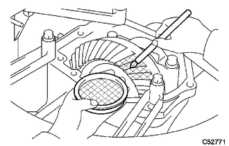
Coat 3 or 4 teeth at 4 different positions on the ring gear with Prussian blue.
Rotate the ring gear 10 times or more.
Rotate the ring gear to inspect the tooth contact pattern.
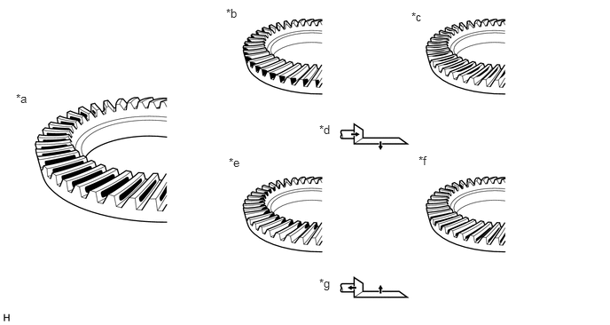
| *a | Proper Contact | *b | Heel Contact |
| *c | Face Contact | *d | Select an adjusting washer that will shift the drive pinion closer to the ring gear (*b, *c) |
| *e | Toe Contact | *f | Flank Contact |
| *g | Select an adjusting washer that will shift the drive pinion away from the ring gear (*e, *f) | - | - |
If the tooth contact pattern is not correct, select a new transfer output shaft washer that is thicker or thinner as necessary and recheck.
4.INSPECT RUNOUT OF RING GEAR
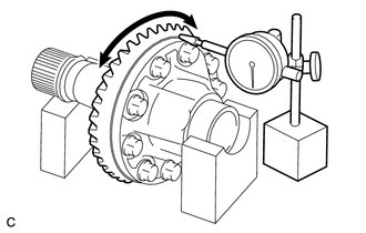
Place the transfer ring gear mounting case on the V-blocks.
Using a dial indicator, check the runout of the ring gear.
- Maximum Runout:
0.06 mm (0.00236 in.)
41319
5.INSPECT TRANSFER RING GEAR MOUNTING CASE
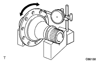
Place the transfer ring gear mounting case on the V-blocks.
Using a dial indicator, check the runout of the ring gear mounting case.
- Maximum Runout:
0.04 mm (0.00157 in.)