DRIVE SHAFT / PROPELLER SHAFT PROPELLER SHAFT ASSEMBLY REASSEMBLY
CAUTION / NOTICE / HINT
- NOTICE:
- ·
When using a vise, place aluminum plates between the part and vise.
·When using a vise, do not overtighten it.
PROCEDURE

 37230J
1.INSTALL NO. 2 CENTER SUPPORT BEARING ASSEMBLY (for Front Side)
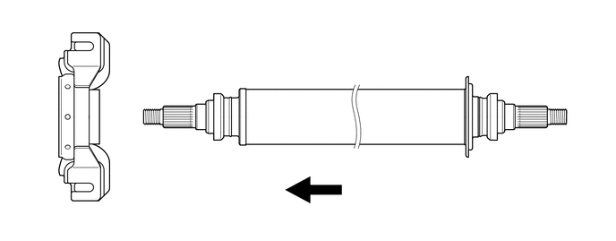
Set the No. 2 center support bearing assembly on the intermediate shaft assembly as shown in the illustration.

|
Front | - | - |
- NOTICE:
-
Make sure to install the No. 2 center support bearing assembly in the correct position.
Install a new washer to the intermediate shaft assembly.
| *a | Matchmark |
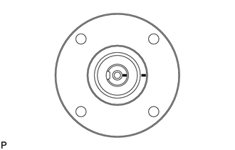
Align the matchmarks on the intermediate shaft assembly and universal joint flange.
| *a | Turn |
| *b | Hold |
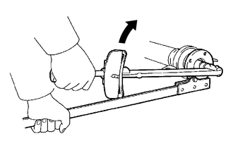
Using SST to hold the universal joint flange, press the No. 2 center support bearing assembly into the position by tightening a new nut and the washer.
- SST
- 09330-00021
- Torque:
- 181.5 N*m (1851 kgf*cm, 134 ft.*lbf)
Loosen the nut.
Tighten the nut again.
- Torque:
- 68.7 N*m (701 kgf*cm, 51 ft.*lbf)
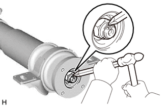
Using a chisel and a hammer, stake the nut.
37230J
2.INSTALL NO. 2 CENTER SUPPORT BEARING ASSEMBLY (for Rear Side)
Set the No. 2 center support bearing assembly on the intermediate shaft assembly as shown in the illustration.
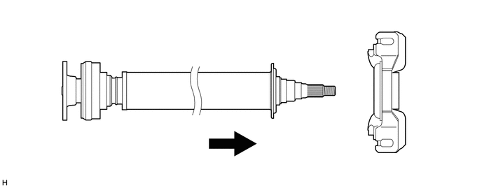
|
|
Rear | - | - |
- NOTICE:
-
Make sure to install the No. 2 center support bearing assembly in the correct position.
Install a new washer to the intermediate shaft assembly.
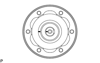
| *a | Matchmark |
Align the matchmarks on the intermediate shaft assembly and universal joint flange.
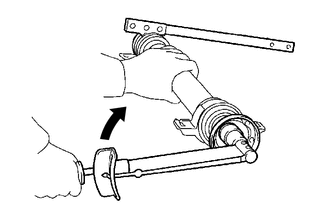
| *a | Turn |
| *b | Hold |
Using SST to hold the universal joint flange, press the No. 2 center support bearing assembly into the position by tightening a new nut and the washer.
- SST
- 09330-00021
- Torque:
- 181.5 N*m (1851 kgf*cm, 134 ft.*lbf)
Loosen the nut.
Tighten the nut again.
- Torque:
- 68.7 N*m (701 kgf*cm, 51 ft.*lbf)
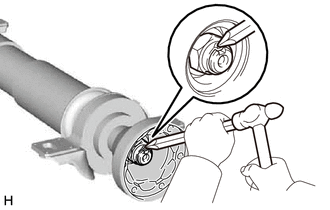
Using a chisel and a hammer, stake the nut.
3.INSTALL INTERMEDIATE SHAFT ASSEMBLY
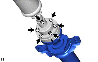
| *a | Matchmark |
Align the matchmarks on the rear propeller shaft assembly and universal joint flange, and then install the 6 cross groove joint set bolts, 2 universal joint washers.
Using a 6 mm hexagon socket wrench, temporarily tighten the 6 cross groove joint set bolts.
4.INSTALL PROPELLER SHAFT ASSEMBLY
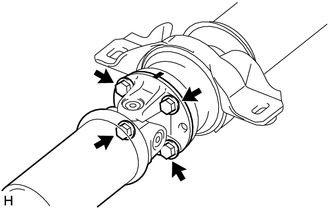
| *a | Matchmark |
Align the matchmarks on the propeller shaft assembly and universal joint flange.
Install the propeller shaft assembly with the 4 bolts, 4 washers and 4 nuts.
- Torque:
- 73.5 N*m (749 kgf*cm, 54 ft.*lbf)
- HINT:
-
Install the washers on the same side as the bolts.
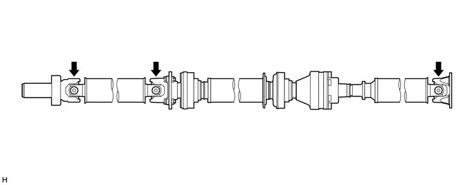
Check that each joint of the propeller with center bearing shaft assembly is facing the direction shown in the illustration.