BRAKE SYSTEM (OTHER) BRAKE MASTER CYLINDER(for RHD) REASSEMBLY
PROCEDURE

 47255
1.INSTALL MASTER CYLINDER RESERVOIR GROMMET
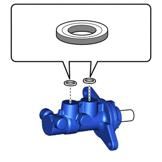

|
Lithium Soap Base Glycol Grease |
Apply a light layer of lithium soap base glycol grease to the entire circumference of 2 new master cylinder reservoir grommets.
Install the 2 master cylinder reservoir grommets to the brake master cylinder body.
47202
2.INSTALL BRAKE MASTER CYLINDER RESERVOIR SUB-ASSEMBLY
Secure the brake master cylinder body in a vise.
- NOTICE:
-
Place aluminum plates on the vise to prevent damage to the brake master cylinder body.
Install the brake master cylinder reservoir sub-assembly to the brake master cylinder body.
- NOTICE:
-
Do not drop the brake master cylinder reservoir sub-assembly.
47201C
3.INSTALL BRAKE MASTER CYLINDER RING PIN
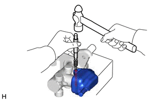
Using a 5 mm pin punch and a hammer, tap in the brake master cylinder ring pin to secure the brake master cylinder reservoir sub-assembly.
Remove the brake master cylinder sub-assembly from the vise.
47201
4.INSTALL BRAKE MASTER CYLINDER SUB-ASSEMBLY
47392A
5.INSTALL NO. 2 BRAKE TUBE WAY
Install the No. 2 brake tube way to the brake master cylinder sub-assembly.
47311K
6.INSTALL BRAKE MASTER CYLINDER TO WAY TUBE
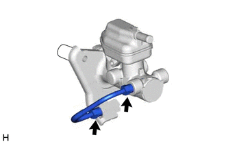
Temporarily install the brake master cylinder to way tube to the brake master cylinder sub-assembly and No. 2 brake tube way.
- NOTICE:
- ·
Tighten the 2 flare nuts by hand.
·Do not kink or damage the brake line.
·Do not allow any foreign matter such as dirt or dust to enter the brake line from the connecting parts.
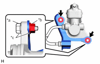
| *a | Bolt |
| *b | Nut |
| *c | Washer |
Secure the No. 2 brake tube way to the brake master cylinder sub-assembly with the 2 bolts, 2 nuts and 4 washers as shown in the illustration.
- Torque:
- 12.5 N*m (127 kgf*cm, 9 ft.*lbf)
Secure the brake master cylinder sub-assembly with way in a vise.
- NOTICE:
-
Place aluminum plates on the vise to prevent damage to the brake master cylinder sub-assembly and No. 2 brake tube way.
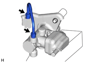
Using a union nut wrench, fully tighten the brake master cylinder to way tube.
- Torque:
- 19.6 N*m (200 kgf*cm, 14 ft.*lbf)
- NOTICE:
-
Use the formula to calculate special torque values for situations where the union nut wrench is combined with a torque wrench.
-
Click hereGeneral>INTRODUCTION>REPAIR INSTRUCTION>PRECAUTION
Remove the brake master cylinder sub-assembly with way from the vise.
Remove the 2 bolts, 2 nuts and 4 washers.