DOOR / HATCH BACK DOOR ADJUSTMENT
CAUTION / NOTICE / HINT
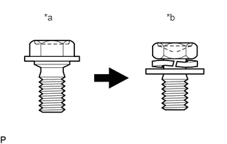
| *a | Centering Bolt |
| *b | Standard Bolt |
- HINT:
- ·
Centering bolts are used to mount the door hinge to the vehicle body and door. The door cannot be adjusted with the centering bolts installed. Substitute the centering bolts with standard bolts (with washers) when making adjustments.
·Specified torque for standard bolts is shown in the standard bolt chart.
Click hereGeneral>SPECIFICATIONS>STANDARD BOLT>SPECIFIED TORQUE FOR STANDARD BOLTS
PROCEDURE

 1.INSPECT BACK DOOR
Check that the clearance measurements of areas "a" through "m" are within each standard range.
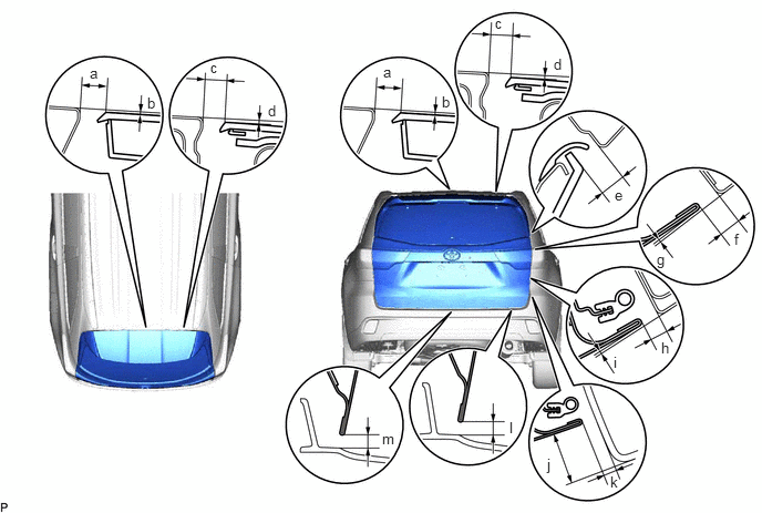
| Area | Measurement | Area | Measurement |
|---|---|---|---|
| a | 9.0 to 13.0 mm (0.354 to 0.512 in.) | b | 0 to 3.5 mm (0.00 to 0.138 in.) |
| c | 7.4 to 11.4 mm (0.291 to 0.449 in.) | d | 0 to 3.5 mm (0.00 to 0.138 in.) |
| e | 6.0 to 10.0 mm (0.236 to 0.394 in.) | f | 5.4 to 8.4 mm (0.213 to 0.331 in.) |
| g | 0.2 to 3.2 mm (0.00787 to 0.126 in.) | h | 4.8 to 7.8 mm (0.189 to 0.307 in.) |
| i | -0.4 to 2.6 mm (-0.0157 to 0.102 in.) | j | 21.5 to 25.5 mm (0.847 to 1.00 in.) |
| k | 4.3 to 8.3 mm (0.169 to 0.327 in.) | l | 4.8 to 8.8 mm (0.189 to 0.346 in.) |
| m | 4.8 to 8.8 mm (0.189 to 0.346 in.) | - | - |
58410B
2.REMOVE DECK BOARD ASSEMBLY
58409A
3.REMOVE NO. 3 DECK BOARD SUB-ASSEMBLY
64742C
4.REMOVE DECK SIDE TRIM BOX LH
64993
5.REMOVE REAR DECK FLOOR BOX
58387B
6.REMOVE REAR FLOOR FINISH PLATE
7.ADJUST BACK DOOR
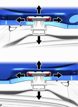
Before adjusting the upper end of the back door up and down or left and right, loosen the 4 bolts.
Tighten the body side hinge after adjustment.
- Torque:
- 19.5 N*m (199 kgf*cm, 14 ft.*lbf)
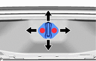
Using a T40 "TORX" socket wrench, slightly loosen the striker mounting 2 screws.
Using a brass bar and a hammer, hit the striker to adjust its position.
Using a T40 "TORX" socket wrench, tighten the striker mounting 2 screws after adjustment.
- Torque:
- 23 N*m (235 kgf*cm, 17 ft.*lbf)
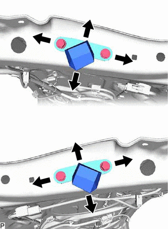
After adjusting the back door position, adjust the position of the back door lower stoppers.
- Torque:
- 7.5 N*m (76 kgf*cm, 66 in.*lbf)
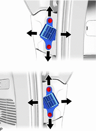
After adjusting the back door position, adjust the position of the back door stopper brackets.
- Torque:
- 7.5 N*m (76 kgf*cm, 66 in.*lbf)
58387B
8.INSTALL REAR FLOOR FINISH PLATE
64993
9.INSTALL REAR DECK FLOOR BOX
64742C
10.INSTALL DECK SIDE TRIM BOX LH
58409A
11.INSTALL NO. 3 DECK BOARD SUB-ASSEMBLY
58410B
12.INSTALL DECK BOARD ASSEMBLY