REAR SUSPENSION REAR STABILIZER BAR INSTALLATION
PROCEDURE

 48818
1.INSTALL REAR STABILIZER BUSHING
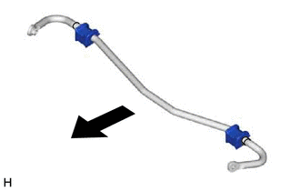
| *a | Stopper |

|
Front of the Vehicle |
Install the 2 rear stabilizer bushings to the inside of the stoppers on the rear stabilizer bar.
48832A
2.INSTALL REAR NO. 1 STABILIZER BAR BRACKET
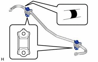
| *a | Identification Shape |
| *b | Identification Mark |
Install the 2 rear No. 1 stabilizer bar brackets to the 2 rear stabilizer bushings.
- NOTICE:
- ·
Ensure that the identification shape faces upward.
·Ensure that the identification mark faces the right side of the vehicle.
48812
3.INSTALL REAR STABILIZER BAR
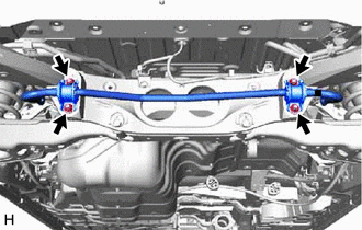
| *a | Identification Mark |
Install the rear stabilizer bar, 2 rear No. 1 stabilizer bar brackets and 2 rear stabilizer bushings to the rear suspension member sub-assembly with the 4 nuts.
- Torque:
- 75 N*m (765 kgf*cm, 55 ft.*lbf)
- NOTICE:
-
Ensure that the identification mark faces the right side of the vehicle.
48802
4.INSTALL REAR STABILIZER LINK SUB-ASSEMBLY LH
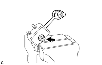
Secure the rear lower stabilizer bracket LH in a vise using aluminum plates.
- NOTICE:
-
Do not overtighten the vise.
Install the rear stabilizer link sub-assembly LH to the rear lower stabilizer bracket LH with the nut.
- Torque:
- 90 N*m (918 kgf*cm, 66 ft.*lbf)
- HINT:
-
If the ball joint turns together with the nut, use a 6 mm hexagon socket wrench to hold the stud bolt.
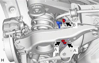
Install the rear stabilizer link sub-assembly LH to the rear stabilizer bar with the nut (B).
- Torque:
- 90 N*m (918 kgf*cm, 66 ft.*lbf)
- HINT:
-
If the ball joint turns together with the nut, use a 6 mm hexagon socket wrench to hold the stud bolt.
Install the rear stabilizer link sub-assembly LH to the rear No. 2 suspension arm assembly LH with the 2 nuts (A).
- Torque:
- 82 N*m (836 kgf*cm, 60 ft.*lbf)
48802
5.INSTALL REAR STABILIZER LINK SUB-ASSEMBLY RH
- HINT:
-
Perform the same procedure as for the LH side.
6.INSTALL REAR WHEEL
- Torque:
- 103 N*m (1050 kgf*cm, 76 ft.*lbf)