RM3160E
_51
Engine / Hybrid System
_019663
2GR-FE ENGINE MECHANICAL
_0109585
CYLINDER BLOCK
A
2GR-FE ENGINE MECHANICAL CYLINDER BLOCK REPLACEMENT
PROCEDURE

 1.REPLACE STRAIGHT PIN
a.
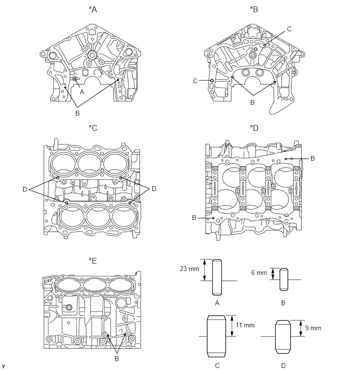
Using a plastic hammer, tap in new straight pins to the cylinder block sub-assembly.
2.292,7.146 2.49,7.51
2.49,7.51 2.656,7.115
false
1.208,3.771 0.615,4.031
0.615,4.031 1.396,4.313
false
2.583,3.771 3.177,4.01
3.177,4.01 2.781,4.292
false
4.521,4.635 4.208,4.635
false
6.094,3.375 6.573,3.375
false
4.938,1.646 5.385,2.031
5.385,2.031 5.844,1.74
false
4.479,1.708 4.229,1.708
false
5.646,0.948 6.063,0.656
false
1.594,1.688 1.698,1.854
false
1.385,1.865 1.646,2.281
1.646,2.281 2.51,1.698
false
1.885,5.438 2.5,5.823
0.615,0.385
12
false
*E
1.885,2.615 2.271,2.948
0.385,0.333
12
false
*C
5.313,2.615 5.896,3.083
0.583,0.469
12
false
*D
1.885,0.094 2.281,0.5
0.396,0.406
12
false
*A
5.313,0.094 5.698,0.625
0.385,0.531
12
false
*B
1.698,1.865 1.854,2.021
0.156,0.156
10
false
A
4.573,6.354 4.729,6.51
0.156,0.156
10
false
A
1.604,2.323 1.76,2.479
0.156,0.156
10
false
B
5.323,2.094 5.479,2.25
0.156,0.156
10
false
B
4.083,4.542 4.208,4.698
0.125,0.156
10
false
B
5.979,6.354 6.135,6.51
0.156,0.156
10
false
B
2.438,7.542 2.594,7.698
0.156,0.156
10
false
B
3.229,3.927 3.385,4.083
0.156,0.156
10
false
D
0.479,3.938 0.635,4.094
0.156,0.156
10
false
D
5.979,7.688 6.135,7.844
0.156,0.156
10
false
D
6.604,3.281 6.76,3.438
0.156,0.156
10
false
B
4.104,1.635 4.26,1.792
0.156,0.156
10
false
C
4.573,7.688 4.729,7.844
0.156,0.156
10
false
C
6.104,0.531 6.26,0.688
0.156,0.156
10
false
C
3.823,5.625 4.292,5.792
0.469,0.167
10
false
23 mm
5.344,5.708 5.729,5.875
0.385,0.167
10
false
6 mm
5.01,6.823 5.469,6.99
0.458,0.167
10
false
11 mm
6.49,6.885 6.896,7.042
0.406,0.156
10
false
9 mm
| *A | Front Side | *B | Rear Side |
| *C | Upper Side | *D | Lower Side |
| *E | RH Side | - | - |
- Standard Protrusion:
Item Protrusion Pin A 23 mm (0.906 in.) Pin B 6 mm (0.236 in.) Pin C 11 mm (0.433 in.) Pin D 9 mm (0.354 in.)
2.REPLACE STUD BOLT
a.
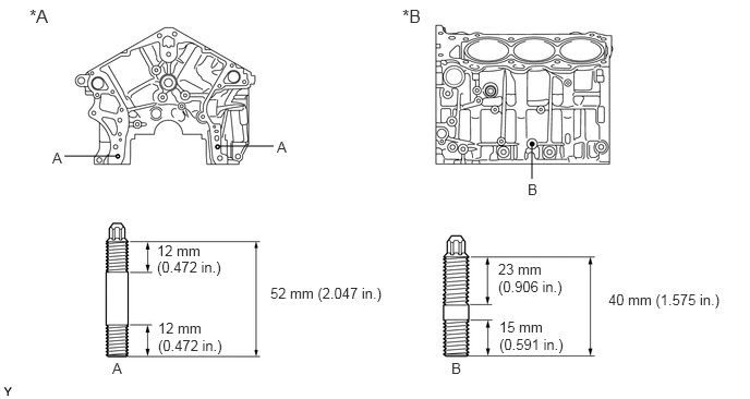
Using E8 and E10 "TORX" socket wrenches, install the stud bolts.
1.115,1.49 0.615,1.49
false
2.094,1.396 2.615,1.396
false
5.083,1.385 5.083,1.708
false
1.073,3.438 1.208,3.583
0.135,0.146
10
false
A
2.583,2.719 3.729,2.896
1.146,0.177
10
false
52 mm (2.047 in.)
5.813,2.781 7.01,2.958
1.198,0.177
10
false
40 mm (1.575 in.)
2.646,1.323 2.781,1.469
0.135,0.146
10
false
A
0.5,1.427 0.635,1.573
0.135,0.146
10
false
A
4.313,3.438 4.438,3.583
0.125,0.146
10
false
B
5.042,1.729 5.167,1.875
0.125,0.146
10
false
B
0.281,0.052 0.667,0.406
0.385,0.354
12
false
*A
3.844,0.052 4.156,0.438
0.313,0.385
12
false
*B
4.76,2.49 5.26,2.646
0.5,0.156
10
false
23 mm
4.771,3.042 5.26,3.188
0.49,0.146
10
false
15 mm
1.5,2.313 1.979,2.479
0.479,0.167
10
false
12 mm
1.51,3.052 1.99,3.219
0.479,0.167
10
false
12 mm
1.51,3.219 2.188,3.396
0.677,0.177
10
false
(0.472 in.)
4.76,2.656 5.448,2.823
0.688,0.167
10
false
(0.906 in.)
4.771,3.208 5.51,3.385
0.74,0.177
10
false
(0.591 in.)
1.5,2.469 2.177,2.646
0.677,0.177
10
false
(0.472 in.)
| *A | Front Side | *B | LH Side |
- Torque:
- Bolt (A) : 10 N*m (102 kgf*cm, 7 ft.*lbf)
- Bolt (B) : 17 N*m (173 kgf*cm, 13 ft.*lbf)
3.REPLACE CONNECTING ROD SMALL END BUSH
a.
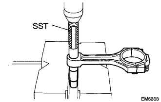
Using SST and a press, press out the bush.
- SST
- 09222-30010
b.
2.635,1.094 2.927,1.344
0.292,0.25
10
false
*a
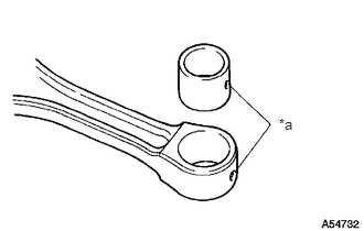
| *a | Oil Hole |
Align the oil holes of a new bush and the connecting rod.
c.
Using SST and a press, press in the bush.
- SST
- 09222-30010
d.
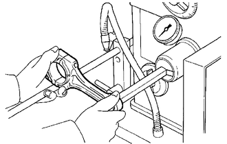
Using a pin hole grinder, hone the bush to obtain the standard oil clearance between the bush and piston pin.
- Standard Oil Clearance:
0.001 to 0.007 mm (0.0000394 to 0.000276 in.)
e.
Coat the piston pin with engine oil, and push it into the connecting rod with a thumb.
- HINT:
-
Check that the piston pin fits at a normal room temperature.