Home › Drivetrain › U660F AUTOMATIC TRANSMISSION / TRANSAXLE › AUTOMATIC TRANSAXLE SYSTEM › 2013.12–2016.11
RM3160E _52 Drivetrain _019726 U660F AUTOMATIC TRANSMISSION / TRANSAXLE _0109808 AUTOMATIC TRANSAXLE SYSTEM J

U660F AUTOMATIC TRANSMISSION / TRANSAXLE  AUTOMATIC TRANSAXLE SYSTEM  Transmission Control Switch Circuit  


DESCRIPTION

When the shift lever is in S and it is moved toward "-" or "+", it is possible to select different shift ranges (1st through 6th range).

Moving the shift lever toward "+" increases the shift range by one, and moving the shift lever toward "-" decreases the shift range by one.

WIRING DIAGRAM
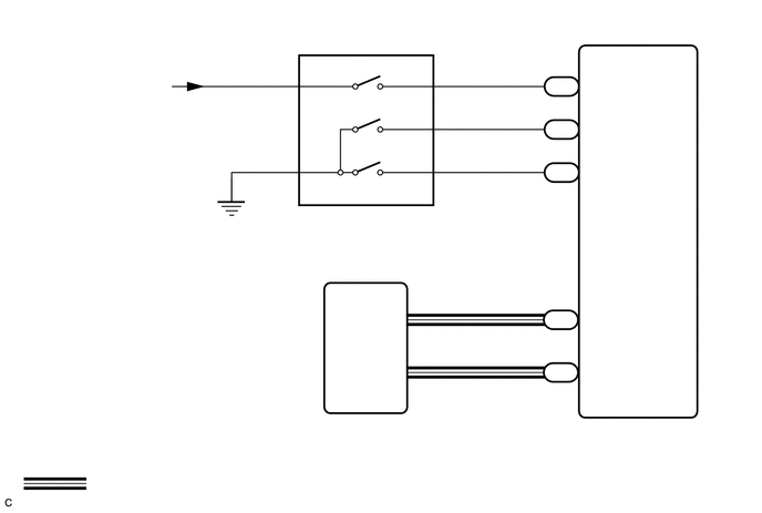
C301527
5.5,0.729 5.656,0.927 0.156,0.198 10 false S 5.5,1.135 6.115,1.333 0.615,0.198 10 false SFTU 5.49,1.552 6.104,1.75 0.615,0.198 10 false SFTD 5.51,2.927 6.125,3.125 0.615,0.198 10 false CAN+ 5.51,3.417 6.125,3.615 0.615,0.198 10 false CAN- 5.156,0.729 5.615,0.927 0.458,0.198 10 false A43 5.156,1.135 5.615,1.333 0.458,0.198 10 false A43 5.156,1.542 5.615,1.74 0.458,0.198 10 false A43 5.177,2.917 5.49,3.115 0.313,0.198 10 false C1 5.188,3.417 5.5,3.615 0.313,0.198 10 false C1 5.833,3.99 6.292,4.188 0.458,0.198 10 false ECM 4.125,0.615 4.281,0.813 0.156,0.198 10 false 7 4.125,1.031 4.281,1.229 0.156,0.198 10 false 2 4.115,1.438 4.271,1.635 0.156,0.198 10 false 1 2.688,0.615 2.844,0.813 0.156,0.198 10 false 3 2.688,1.438 2.844,1.635 0.156,0.198 10 false 5 3.927,0.635 4.083,0.833 0.156,0.198 10 false S 3.688,1.042 4.302,1.24 0.615,0.198 10 false SFTU 3.688,1.438 4.302,1.635 0.615,0.198 10 false SFTD 2.865,0.625 3.177,0.823 0.313,0.198 10 false IG 2.865,1.438 3.115,1.719 0.25,0.281 10 false E 0.385,0.729 1.781,1.083 1.396,0.354 10 false from IG1 NO.3 fuse 0.865,4.469 4.531,4.667 3.667,0.198 10 false : CAN Communication Line 5.198,2.74 5.51,2.938 0.313,0.198 10 false 31 5.24,3.229 5.396,3.427 0.156,0.198 10 false 1 3.875,2.771 4.031,2.969 0.156,0.198 10 false 6 3.885,3.25 4.042,3.448 0.156,0.198 10 false 7 3.427,2.917 4.042,3.115 0.615,0.198 10 false CAN+ 3.448,3.406 4.063,3.604 0.615,0.198 10 false CAN- 3.135,3.958 3.448,4.156 0.313,0.198 10 false C3 3.396,3.958 3.854,4.156 0.458,0.198 10 false TCM 2.49,1.865 2.948,2.063 0.458,0.198 10 false F46 2.479,2.021 4.323,2.583 1.844,0.563 10 false Lower Shift Lever Assembly (Transmission Control Switch) 5.198,0.542 5.698,0.823 0.5,0.281 10 false 37 5.198,0.958 5.51,1.156 0.313,0.198 10 false 34 5.208,1.365 5.521,1.563 0.313,0.198 10 false 50

CAUTION / NOTICE / HINT

NOTICE:

Inspect the fuses for circuits related to this system before performing the following inspection procedure.


HINT:
·

Refer to inspection procedure for CAN communication system.

·

If the CAN communication system is malfunctioning, the TCM cannot receive current data from the ECM. In this case, the freeze frame data output from the TCM has not been updated, so it will not be useful for inspection. However, reading the Data List as the first step in troubleshooting is effective to find malfunctions.

·

The malfunction area can be checked using the Bus Check function on the GTS.

Click herePower Source / Network>NETWORKING>CAN COMMUNICATION SYSTEM>HOW TO PROCEED WITH TROUBLESHOOTING


PROCEDURE
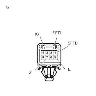
1.CHECK HARNESS AND CONNECTOR (BATTERY - TRANSMISSION CONTROL SWITCH)
a.
C168574
0.406,1.375 0.896,1.646 0.49,0.271 1.844,2.094 2.427,1.729 false 0.135,0.229 0.479,0.563 0.344,0.333 10 false *a 2.531,1.635 2.844,1.833 0.313,0.198 10 false IG 0.542,1.417 1.042,1.677 0.5,0.26 10 false F46
*a Front view of wire harness connector
(to Transmission Control Switch)


Disconnect the transmission control switch connector.

b.

Measure the voltage according to the value(s) in the table below.

Standard Voltage:
Tester Connection Condition Specified Condition
F46-3 (IG) - Body ground Ignition switch ON 11 to 14 V
Ignition switch off Below 1 V


Result:
Proceed to
OK
NG


OK

2.CHECK HARNESS AND CONNECTOR (TRANSMISSION CONTROL SWITCH - BODY GROUND)

NG

CHECK POWER SOURCE CIRCUIT

2.CHECK HARNESS AND CONNECTOR (TRANSMISSION CONTROL SWITCH - BODY GROUND)
a.
C168574
0.406,1.375 0.896,1.646 0.49,0.271 0.813,2.708 1.396,2.344 false 0.135,0.229 0.479,0.563 0.344,0.333 10 false *a 0.531,2.708 0.844,2.906 0.313,0.198 10 false E 0.552,1.417 1.052,1.677 0.5,0.26 10 false F46
*a Front view of wire harness connector
(to Transmission Control Switch)


Measure the resistance according to the value(s) in the table below.

Standard Resistance:
Tester Connection Condition Specified Condition
F46-5 (E) - Body ground Always Below 1 Ω


Result:
Proceed to
OK
NG


OK

3.INSPECT TRANSMISSION FLOOR SHIFT ASSEMBLY (TRANSMISSION CONTROL SWITCH)

NG

REPAIR OR REPLACE HARNESS OR CONNECTOR

3.INSPECT TRANSMISSION FLOOR SHIFT ASSEMBLY (TRANSMISSION CONTROL SWITCH)
a.
C168599C01
1.646,1.854 1.438,1.323 true 1.25,2.521 1.667,2.104 true 1.875,1.833 2.042,1.333 true 2.031,1.885 2.438,1.656 true 2.313,2.458 2.031,2.104 true 0.208,0.198 0.583,0.49 0.375,0.292 10 false *a 1.25,1.135 1.563,1.333 0.313,0.198 10 false IG 1.021,2.5 1.333,2.698 0.313,0.198 10 false S 1.885,1.094 2.427,1.344 0.542,0.25 10 false SFTU 2.427,1.458 2.969,1.708 0.542,0.25 10 false SFTD 2.438,2.396 2.75,2.594 0.313,0.198 10 false E
*a Component without harness connected
(Transmission Control Switch)


Measure the resistance between each terminal of the transmission control switch when the shift lever is moved to each position.

Standard Resistance:
Tester Connection Condition Specified Condition
F46-3 (IG) - F46-7 (S) Shift lever in S, "+" or "-" Below 1 Ω
Shift lever not in S, "+" or "-" 10 kΩ or higher
F46-2 (SFTU) - F46-5 (E) Shift lever held in "+"
(Up-shift)
Below 1 Ω
Shift lever not held in "+" 10 kΩ or higher
F46-1 (SFTD) - F46-5 (E) Shift lever held in "-"
(Down-shift)
Below 1 Ω
Shift lever not held in "-" 10 kΩ or higher


Result:
Proceed to
OK
NG


OK

4.CHECK HARNESS AND CONNECTOR (TRANSMISSION CONTROL SWITCH - ECM)

NG

REPLACE TRANSMISSION FLOOR SHIFT ASSEMBLY (TRANSMISSION CONTROL SWITCH)

4.CHECK HARNESS AND CONNECTOR (TRANSMISSION CONTROL SWITCH - ECM)
a.

Connect the transmission control switch connector.


b.
C233487
0.094,1.01 0.51,1.302 0.417,0.292 1.656,1.25 2.01,1.875 2.01,1.875 2.146,1.875 false 1.427,1.25 1.135,0.406 1.135,0.406 0.906,0.406 false 1.5,1.333 1.24,1.896 1.24,1.896 1.115,1.896 false 0.167,0.125 0.531,0.281 0.365,0.156 10 false *a 0.198,1.073 0.719,1.469 0.521,0.396 10 false A43 2.198,1.802 2.333,1.958 0.135,0.156 10 false S 0.521,0.333 0.938,0.49 0.417,0.156 10 false SFTU 0.719,1.813 1.135,1.969 0.417,0.156 10 false SFTD
*a Front view of wire harness connector
(to ECM)


Disconnect the ECM connector.


c.

Turn the ignition switch to ON.


d.

Measure the voltage according to the value(s) in the table below.

Standard Voltage:
Tester Connection Condition Specified Condition
A43-37 (S) - Body ground
·

Ignition switch ON

·

Shift lever in S, "+" or "-"


11 to 14 V
A43-37 (S) - Body ground
·

Ignition switch ON

·

Shift lever not in S, "+" or "-"


Below 1 V


e.

Turn the ignition switch off.


f.

Measure the resistance according to the value(s) in the table below.

Standard Resistance:
Tester Connection Condition Specified Condition
A43-34 (SFTU) - Body ground Shift lever held in "+"
(Up-shift)
Below 1 Ω
Shift lever not held in "+" 10 kΩ or higher
A43-50 (SFTD) - Body ground Shift lever held in "-"
(Down-shift)
Below 1 Ω
Shift lever not held in "-" 10 kΩ or higher


Result:
Proceed to
OK
NG


OK

PROCEED TO NEXT SUSPECTED AREA SHOWN IN PROBLEM SYMPTOMS TABLE

NG

REPAIR OR REPLACE HARNESS OR CONNECTOR