HEATING / AIR CONDITIONING REAR AIR CONDITIONING UNIT REASSEMBLY
PROCEDURE

 88501R
1.INSTALL REAR EVAPORATOR SUB-ASSEMBLY
Sufficiently apply compressor oil to 2 new O-rings and the fitting surfaces of the rear evaporator sub-assembly.
- Compressor Oil:
ND-OIL 8 or equivalent
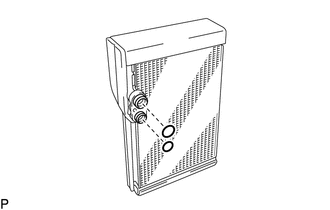
Install the 2 O-rings to the rear evaporator sub-assembly.
- NOTICE:
-
Keep the O-rings and O-ring fitting surfaces free from dirt and foreign matter.
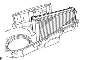
Install the rear evaporator sub-assembly.
82210L
2.INSTALL NO. 2 AIR CONDITIONING HARNESS ASSEMBLY
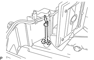
Engage the 2 claws.
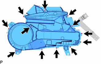
Install the rear cooling unit cover LH with the 12 screws.
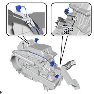
Engage each clamp to install the No. 2 air conditioning harness assembly.
87106W
3.INSTALL REAR AIR MIX DAMPER SERVO SUB-ASSEMBLY
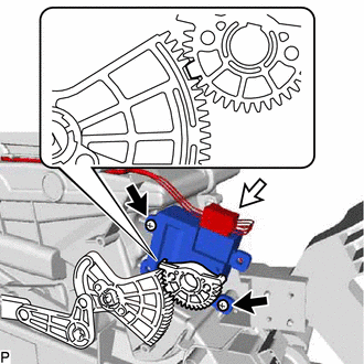
| *a | Reference Point |
Using the reference points, install the rear air mix damper servo sub-assembly with the 2 screws.
Connect the connector.
87106X
4.INSTALL REAR MODE DAMPER SERVO SUB-ASSEMBLY
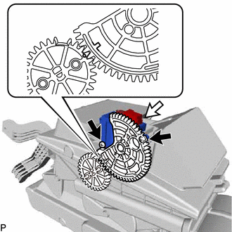
| *a | Reference Point |
Using the reference points, install the rear mode damper servo sub-assembly with the 2 screws.
Connect the connector.
87165C
5.INSTALL BLOWER MOTOR CONTROL
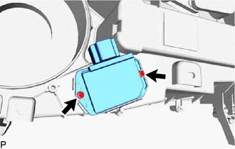
Install the blower motor control with the 2 screws.
87103D
6.INSTALL REAR BLOWER MOTOR WITH FAN SUB-ASSEMBLY
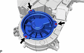
Install the rear blower motor with fan sub-assembly with the 3 screws.
- NOTICE:
-
Do not install the rear blower motor with fan sub-assembly if it has been dropped or subjected to a severe impact.
87107B
7.INSTALL HEATER RADIATOR UNIT SUB-ASSEMBLY
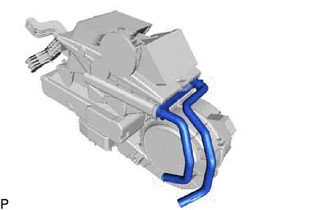
Install the heater radiator unit sub-assembly.
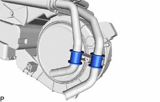
Install the 2 bushes.
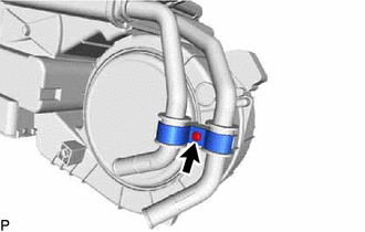
Install the clamp with the screw.
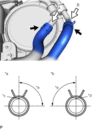
| *a | View A |
| *b | View B |
| *c | Marking (Blue) |
| *d | Marking (Pink) |
| *e | Clip Installation Angle (60 to 120°) |
Connect the heater water pipe and hose sub-assembly and engage the 2 clips within the area shown in the illustration.
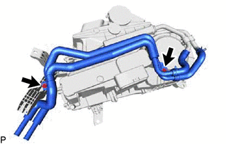
Install the heater water pipe and hose sub-assembly with the 2 screws.
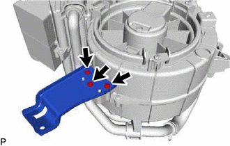
Install the bracket with the 3 screws.
88515B
8.INSTALL REAR COOLING UNIT EXPANSION VALVE
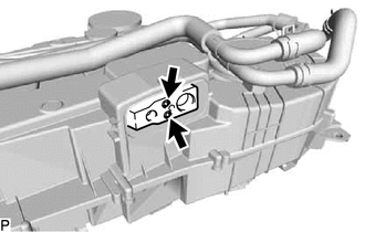
Using a 4 mm hexagon wrench, install the rear cooling unit expansion valve with the 2 hexagon bolts.
- Torque:
- 3.5 N*m (36 kgf*cm, 31 in.*lbf)
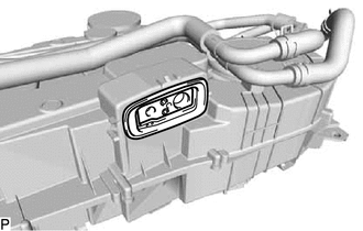
Install the grommet.
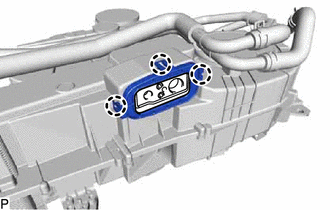
Engage the 3 claws to install the plate.
Remove the vinyl tape from the air conditioner tube and accessory assembly.
Sufficiently apply compressor oil to 2 new O-rings and the fitting surfaces of the air conditioner tube and accessory assembly.
- Compressor Oil:
ND-OIL 8 or equivalent
Install the 2 O-rings to the air conditioner tube and accessory assembly.
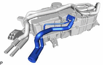
Temporarily install the air conditioner tube and accessory assembly.
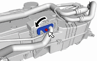
Rotate the hook connector as shown in the illustration.
Insert the tube joint into the fitting hole securely and using a 4 mm hexagon wrench, tighten the hexagon bolt.
- Torque:
- 9.8 N*m (100 kgf*cm, 87 in.*lbf)
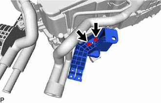
Install the bracket with the 2 screws.
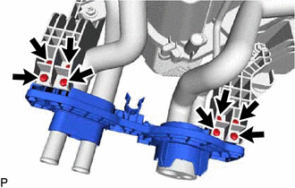
Install the cover with the 8 screws.
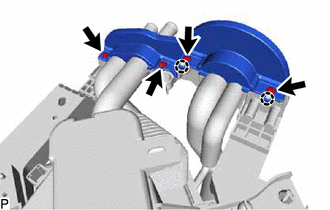
Engage the 2 claws.
Install the cover with the 4 screws.
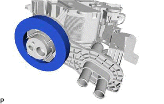
Install a new packing.
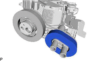
Install a new packing.
9.INSTALL NO. 1 COOLING UNIT PACKING
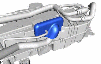
Install a new No. 1 cooling unit packing.
88539K
10.INSTALL DRAIN COOLER HOSE
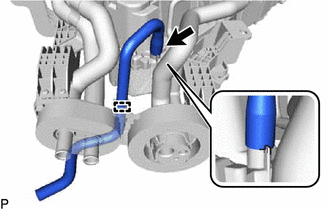
| *a | Hose Notch |
| *b | Rear Cooling Unit Assembly Rib |
Align the hose notch with the rear cooling unit assembly rib as shown in the illustration and install the drain cooler hose.
Engage the clamp.