Home › Engine / Hybrid System › CRUISE CONTROL › CRUISE CONTROL SYSTEM › from 2016.11
RM3160E _51 Engine / Hybrid System _019684 CRUISE CONTROL _0109815 CRUISE CONTROL SYSTEM C

CRUISE CONTROL  CRUISE CONTROL SYSTEM  P0571  Brake Switch "A" Circuit  


DESCRIPTION

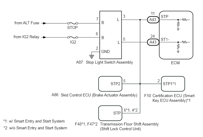
When the brake pedal is depressed, the stop light switch assembly sends a signal to the ECM. When the ECM receives this signal, it cancels control of vehicle speed by the cruise control system. The fail-safe function operates to enable normal driving even if there is a malfunction in the stop light switch assembly signal circuit. The cancellation condition occurs when voltage is applied to terminal STP. When the brake pedal is depressed, voltage is applied to terminal STP of the ECM through the STOP fuse and the stop light switch assembly, and the ECM cancels control of vehicle speed by the cruise control system.

DTC No. Detection Item DTC Detection Condition Trouble Area
P0571 Brake Switch "A" Circuit When the ignition switch is ON and the cruise control system is operating, the voltage of the STP and ST1- terminals of the ECM are less than 1 V for 0.5 seconds or more.
·

Stop light switch assembly

·

Harness or connector

·

ECM


WIRING DIAGRAM

A395927E02
6.042,2.125 6.5,2.323 0.458,0.198 10 false ECM 5.271,0.604 5.729,0.802 0.458,0.198 10 false A43 5.281,1.396 5.74,1.594 0.458,0.198 10 false A43 5.677,0.5 6.135,0.698 0.458,0.198 10 false STP 5.677,1.302 6.135,1.5 0.458,0.198 10 false ST1- 5.323,0.385 5.781,0.583 0.458,0.198 10 false 11 5.313,1.188 5.771,1.385 0.458,0.198 10 false 24 5.385,3.281 6.906,3.677 1.521,0.396 10 false Certification ECU (Smart Key ECU Assembly)*1 5.094,3.281 5.552,3.479 0.458,0.198 10 false F10 5.75,2.865 6.302,3.063 0.552,0.198 10 false STP1*1 5.563,2.76 6.021,2.958 0.458,0.198 10 false 2 3.531,4.281 5.688,4.646 2.156,0.365 10 false Transmission Floor Shift Assembly (Shift Lock Control Unit) 2.646,4.281 3.656,4.479 1.01,0.198 10 false F48*1, F47*2 4,3.896 4.458,4.094 0.458,0.198 10 false STP 4.375,3.792 5.073,3.979 0.698,0.188 10 false 6*1, 4*2 2.146,3.26 5,3.5 2.854,0.24 10 false Skid Control ECU (Brake Actuator Assembly) 1.823,3.25 2.281,3.448 0.458,0.198 10 false A86 3.906,2.865 4.365,3.063 0.458,0.198 10 false STP2 4.354,2.76 4.813,2.958 0.458,0.198 10 false 5 3.573,1.729 4.031,1.927 0.458,0.198 10 false GND 3.031,2.104 4.896,2.323 1.865,0.219 10 false Stop Light Switch Assembly 2.688,2.104 3.146,2.302 0.458,0.198 10 false A87 3.385,1.615 3.844,1.813 0.458,0.198 10 false 2 3.583,1.24 4.042,1.438 0.458,0.198 10 false B 3.583,0.708 4.042,0.906 0.458,0.198 10 false B 3.385,1.104 3.844,1.302 0.458,0.198 10 false 6 3.396,0.583 3.854,0.781 0.458,0.198 10 false 7 2.469,1.396 2.927,1.594 0.458,0.198 10 false IG2 2.375,0.885 2.833,1.083 0.458,0.198 10 false STOP 0.479,1.208 1.688,1.458 1.208,0.25 10 false from IG2 Relay 0.51,0.719 1.958,1.01 1.448,0.292 10 false from ALT Fuse 4.135,0.604 4.594,0.802 0.458,0.198 10 false L 4.156,1.406 4.615,1.604 0.458,0.198 10 false L 4.344,1.292 4.802,1.49 0.458,0.198 10 false 5 4.344,0.49 4.802,0.688 0.458,0.198 10 false 3 0.115,4.177 2.969,4.417 2.854,0.24 10 false *1: w/ Smart Entry and Start System 0.125,4.417 2.979,4.656 2.854,0.24 10 false *2: w/o Smart Entry and Start System

CAUTION / NOTICE / HINT

NOTICE:

Inspect the fuses for circuits related to this system before performing the following procedure.


PROCEDURE
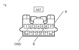
1.CHECK HARNESS AND CONNECTOR (STOP LIGHT SWITCH ASSEMBLY - BATTERY AND BODY GROUND)
a.
A395526C03
1.479,0.302 1.875,0.521 0.396,0.219 0.792,1.823 1.292,1.156 true 1.469,1.844 1.969,1.177 true 2.26,1.156 2.76,0.49 true 0.146,0.135 0.458,0.292 0.313,0.156 10 false *a 0.615,1.844 1.073,2.042 0.458,0.198 10 false GND 1.427,1.844 1.885,2.042 0.458,0.198 10 false B 2.823,0.427 3.281,0.625 0.458,0.198 10 false B 1.552,0.344 2.01,0.542 0.458,0.198 10 false A87
*a Front view of wire harness connector
(to Stop Light Switch Assembly)


Disconnect the A87 stop light switch assembly connector.


b.

Measure the resistance according to the value(s) in the table below.

Standard Resistance:
Tester Connection Condition Specified Condition
A87-2 (GND) - Body ground Always Below 1 Ω


c.

Measure the voltage according to the value(s) in the table below.

Standard Voltage:
Tester Connection Condition Specified Condition
A87-7 (B) - Body ground Always 11 to 14 V
A87-6 (B) - Body ground Ignition switch ON 11 to 14 V
A87-6 (B) - Body ground Ignition switch off Below 1 V


Result:
Proceed to
OK
NG


OK

2.INSPECT STOP LIGHT SWITCH ASSEMBLY

NG

REPAIR OR REPLACE HARNESS OR CONNECTOR

2.INSPECT STOP LIGHT SWITCH ASSEMBLY
a.

Inspect the stop light switch assembly.

Click hereVehicle Exterior>LIGHTING (EXT)>STOP LIGHT SWITCH>ON-VEHICLE INSPECTION


Result:
Proceed to
OK
NG


OK

3.CHECK HARNESS AND CONNECTOR (ECM - STOP LIGHT SWITCH ASSEMBLY)

NG

REPLACE STOP LIGHT SWITCH ASSEMBLY

3.CHECK HARNESS AND CONNECTOR (ECM - STOP LIGHT SWITCH ASSEMBLY)
a.

Disconnect the A43 ECM connector.


b.

Disconnect the A87 stop light switch assembly connector.


c.

Disconnect the A86 skid control ECU (brake actuator assembly) connector.


d.

Disconnect the F10 certification ECU (smart key ECU assembly) connector (w/ Smart Entry and Start System).


e.

Disconnect the F48 transmission floor shift assembly (shift lock control unit) connector (w/ Smart Entry and Start System).


f.

Disconnect the F47 transmission floor shift assembly (shift lock control unit) connector (w/o Smart Entry and Start System).


g.

Measure the resistance according to the value(s) in the table below.

Standard Resistance:
Tester Connection Condition Specified Condition
A43-24 (ST1-) - A87-5 (L) Always Below 1 Ω
A43-11 (STP) - A87-3 (L) Always Below 1 Ω
A43-24 (ST1-) or A87-5 (L) - Body ground Always 10 kΩ or higher
A43-11 (STP) or A87-3 (L) - Body ground Always 10 kΩ or higher


Result:
Proceed to
OK
NG


OK

NG

REPAIR OR REPLACE HARNESS OR CONNECTOR