UA80F AUTOMATIC TRANSMISSION / TRANSAXLE AUTOMATIC TRANSAXLE SYSTEM P271312 Pressure Control Solenoid "D" Circuit Short to Battery
DESCRIPTION
Refer to DTC P27137F.
Click hereDrivetrain>UA80F (AUTOMATIC TRANSMISSION / TRANSAXLE)>AUTOMATIC TRANSAXLE SYSTEM>P27137F
| DTC No. | Detection Item | DTC Detection Condition | Trouble Area | MIL | Memory | Note |
|---|---|---|---|---|---|---|
| P271312 | Pressure Control Solenoid "D" Circuit Short to Battery | 1. Diagnosis Condition 2. Malfunction Status 3. Malfunction Time 4. Other
1.
Engine is running 2.
Solenoid (SLT) valve circuit is short to +B 3.
1 second 4.
1-trip detection logic |
·
Solenoid (SLT) valve ·
Transmission wire ·
Harness and connector ·
ECM |
Comes on | DTC stored | SAE Code:
P2721 |
MONITOR DESCRIPTION
When a short to +B in the solenoid (SLT) valve circuit is detected, the ECM will determine that there is a malfunction, illuminate the MIL and store this DTC.
WIRING DIAGRAM
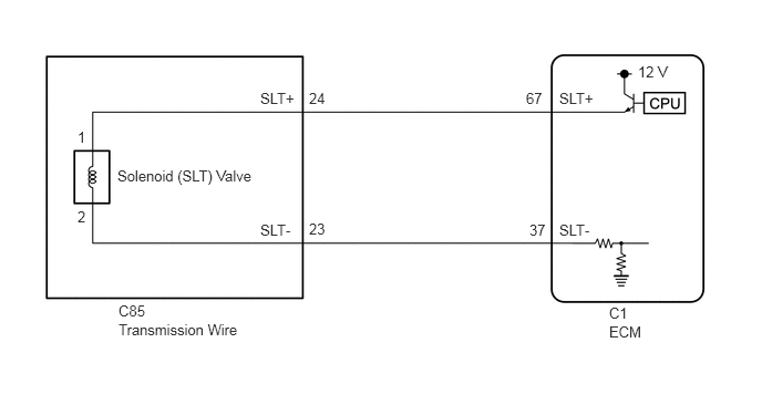
CAUTION / NOTICE / HINT
- NOTICE:
-
Perform registration and/or initialization when parts related to the automatic transaxle are replaced.
-
Click hereDrivetrain>UA80F (AUTOMATIC TRANSMISSION / TRANSAXLE)>AUTOMATIC TRANSAXLE SYSTEM>PRECAUTION
- HINT:
-
After performing repair, clear the DTCs and perform the following procedure to check that DTCs are not output.
- 1.
Start the engine.
2.Check for DTCs again.
Click hereDrivetrain>UA80F (AUTOMATIC TRANSMISSION / TRANSAXLE)>AUTOMATIC TRANSAXLE SYSTEM>DTC CHECK / CLEAR
PROCEDURE
Disconnect the C1 ECM connector.
Measure the resistance according to the value(s) in the table below.
- Standard Resistance:
Tester Connection Condition Specified Condition C1-67 (SLT+) or C1-37 (SLT-) - Other terminals Always 10 kΩ or higher
- Result:
Proceed to OK NG
OK
NG
Replace the ECM.
Click hereEngine / Hybrid System>2GR-FKS (ENGINE CONTROL)>ECM>COMPONENTS
- Result:
Proceed to NEXT
NEXT
Click hereDrivetrain>UA80F (AUTOMATIC TRANSMISSION / TRANSAXLE)>AUTOMATIC TRANSAXLE SYSTEM>REGISTRATION
Disconnect the C85 transmission wire connector.
Disconnect the C1 ECM connector.
Measure the resistance according to the value(s) in the table below.
- Standard Resistance:
Tester Connection Condition Specified Condition C85-24 (SLT+) or C1-67 (SLT+) - Other terminals Always 10 kΩ or higher C85-23 (SLT-) or C1-37 (SLT-) - Other terminals Always 10 kΩ or higher
- Result:
Proceed to OK NG
OK
NG
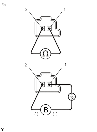
| *a | Component without harness connected
(Solenoid (SLT) Valve) |
Remove the solenoid (SLT) valve.
Click hereDrivetrain>UA80F (AUTOMATIC TRANSMISSION / TRANSAXLE)>VALVE BODY ASSEMBLY>DISASSEMBLY
Measure the resistance according to the value(s) in the table below.
- Standard Resistance:
Tester Connection Condition Specified Condition Solenoid (SLT) valve connector terminal 1 - terminal 2 20°C (68°F) 5.0 to 5.6 Ω
Connect a positive (+) lead from the battery with a 21 W bulb to terminal 1 and a negative (-) lead to terminal 2 of the solenoid valve connector. Check that the valve moves and makes an operating sound.
- OK:
Valve moves and makes an operating sound.
- Result:
Proceed to OK NG
OK
When Not Using the Engine Support Bridge: Click hereDrivetrain>UA80F (AUTOMATIC TRANSMISSION / TRANSAXLE)>TRANSMISSION WIRE(When Not Using the Engine Support Bridge)>COMPONENTS
When Using the Engine Support Bridge: Click hereDrivetrain>UA80F (AUTOMATIC TRANSMISSION / TRANSAXLE)>TRANSMISSION WIRE(When Using the Engine Support Bridge)>COMPONENTS
NG