BODY PANEL FIT STANDARD / ADJUSTMENT METHOD ADJUSTMENT
Refer to the TOYOTA Repair Manual for adjustment method.
- HINT:
-
Vehicle Exterior
INSPECT HOOD SUB-ASSEMBLY
Check that the clearance measurements of areas A to K are within the standard ranges.
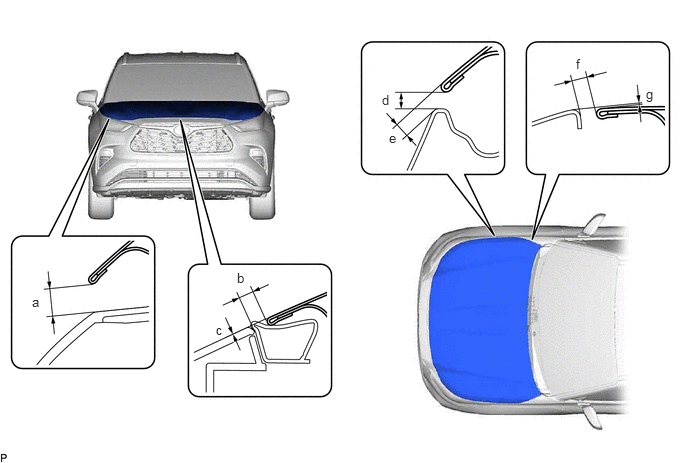
| Area | Measurement | Area | Measurement |
|---|---|---|---|
| a | 7.35 to 11.35 mm (0.289 to 0.447 in.) | b | 2.85 to 6.85 mm (0.112 to 0.270 in.) |
| c | -1.85 to 2.15 mm (-0.0728 to 0.0846 in.) | d | 3.1 to 6.1 mm (0.122 to 0.240 in.) |
| e | 2.1 to 5.1 mm (0.0827 to 0.201 in.) | f | 3.2 to 6.2 mm (0.126 to 0.244 in.) |
| g | 0.5 mm (0.0197 in.) | - | - |
INSPECT FRONT DOOR
Check that the clearance measurements of areas A to L are within the standard ranges.
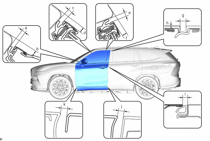
| Area | Measurement | Area | Measurement |
|---|---|---|---|
| a | 3.05 to 6.05 mm (0.120 to 0.238 in.) | b | 6.45 to 9.45 mm (0.254 to 0.372 in.) |
| c | 3.05 to 6.05 mm (0.120 to 0.238 in.) | d | 4.05 to 7.05 mm (0.159 to 0.278 in.) |
| e | 3.05 to 6.05 mm (0.120 to 0.238 in.) | f | 4.25 to 7.25 mm (0.167 to 0.285 in.) |
| g | 2.6 to 6.6 mm (0.102 to 0.260 in.) | h | -1.9 to 2.1 mm (-0.0748 to 0.0827 in.) |
| i | 2.7 to 5.7 mm (0.106 to 0.224 in.) | j | 5.0 to 9.0 mm (0.197 to 0.354 in.) |
| k | 5.0 to 9.0 mm (0.197 to 0.354 in.) | - | - |
- HINT:
- ·
Use the same procedure for the RH and LH sides.
·The procedure below is for the LH side.
·Centering bolts are used to mount the door hinge to the vehicle body and door. The door cannot be adjusted with the centering bolts on. Substitute the centering bolts for standard bolts when making adjustments.
INSPECT REAR DOOR
Check that the clearance measurements of areas A to K are within the standard ranges.
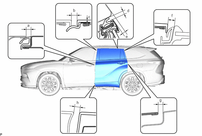
| Area | Measurement | Area | Measurement |
|---|---|---|---|
| a | 2.7 to 5.7 mm (0.106 to 0.224 in.) | b | 2.6 to 6.6 mm (0.102 to 0.260 in.) |
| c | -1.9 to 2.1 mm (-0.0748 to 0.0827 in.) | d | 2.85 to 6.25 mm (0.112 to 0.246 in.) |
| e | 2.25 to 6.25 mm (0.0886 to 0.246 in.) | f | 4.8 to 8.8 mm (0.189 to 0.346 in.) |
| g | 2.6 to 5.6 mm (0.102 to 0.220 in.) | h | 5.0 to 9.0 mm (0.197 to 0.354 in.) |
- HINT:
- ·
Use the same procedure for the RH and LH sides.
·The procedure listed below is for the LH side.
·Centering bolts are used to mount the door hinge to the vehicle body and door. The door cannot be adjusted with the centering bolts on. Substitute the centering bolts for standard bolts when making adjustments.
INSPECT BACK DOOR
Check that the clearance measurements of areas A to H are within the standard ranges.
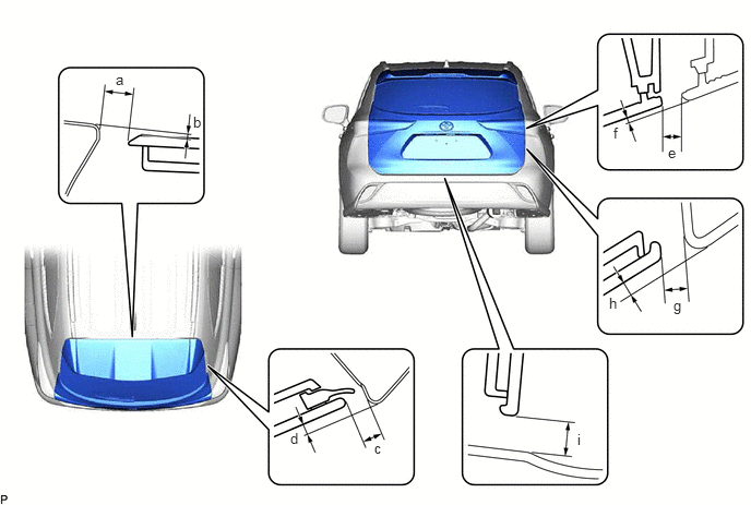
| Area | Measurement | Area | Measurement |
|---|---|---|---|
| a | 6.15 to 10.15 mm (0.242 to 0.400 in.) | b | -0.35 to 3.65 mm (-0.0138 to 0.144 in.) |
| c | 4.05 to 9.05 mm (0.159 to 0.356 in.) | d | 0.95 to 5.95 mm (0.0374 to 0.234 in.) |
| e | 2.9 to 7.9 mm (0.114 to 0.311 in.) | f | -1.0 to 4.0 mm (-0.0394 to 0.158 in.) |
| g | 3.8 to 8.8 mm (0.150 to 0.346 in.) | h | 1.0 to 6.0 mm (0.0394 to 0.236 in.) |
| i | 5.8 to 10.8 mm (0.228 to 0.425 in.) | - | - |
- HINT:
-
Centering bolts are used to mount the door hinge to the vehicle body and door. The door cannot be adjusted with the centering bolts on. Substitute the centering bolts for standard bolts when making adjustments.