HYBRID / BATTERY CONTROL HYBRID BATTERY SYSTEM GENERAL GENERAL
OUTLINE
HV Battery
A Nickel Metal Hydride (Ni-MH) battery has been provided.
A small and high-efficiency hybrid battery has been installed under the rear No. 1 seat.
The new hybrid battery location contributes to excellent handling stability due to a lower center of gravity.
SPECIFICATION
HV Battery
| Item | Specification | |
|---|---|---|
| Type | Nickel Metal Hydride (Ni-MH) Battery | |
| Cell Quantity | 240 Cells (6 Cells x 40 Modules) | |
| Nominal Voltage | V | 288 |
| Battery Capacity (3HR) | Ah | 6.5 |
MAIN FEATURES
Cooling System
By locating air intake vents in the rear door scuff plate under the rear No. 1 seat, air inside the vehicle which has a comparatively lower temperature is drawn in which increases cooling efficiency, thus minimizing battery deterioration and reduced lifespan.
Also, the cooling system was designed with consideration to reducing vibration and noise at ear level of the occupants.
By distributing air that has cooled the battery out under the carpet along the entire the floor, any temperature increases are difficult to be perceived by the occupants.
Air inside the vehicle is drawn in from the left and right intake ports and flows from the intake duct No. 1 to the battery cooling blower assemblies, and then from the battery cooling blower assemblies to the intake duct No. 2 and into the HV battery.
Cooling air flows from the bottom between the hybrid battery modules to the top, and is released from the left and right openings on top of the HV Battery under the carpet after thermal exchange.
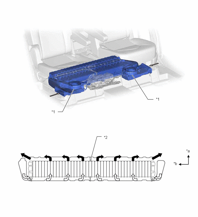
| *1 | Battery Cooling Blower Assembly | *2 | Hybrid Battery Module |
| *a | Upper | *b | Right |

|
Intake | 
|
Exhaust |
An air filter has been provided on the cooling air intake bezel.
- NOTICE:
- ·
Air intake vents are located on the left and right rear door scuff plates in order to cool the hybrid battery.
If the vent becomes blocked, the hybrid battery may overheat, leading to a reduction in hybrid battery output, and be damaged.
·Clean the air intake vent regularly using a vacuum cleaner to prevent the hybrid battery from overheating.
·Do not get water or foreign materials in the air intake vent as this may cause a short circuit and damage the hybrid battery.
·Do not carry large amounts of water such as water cooler bottles in the vehicle. If water spills onto the hybrid battery, the battery may be damaged.
Service Plug Grip
By removing the service plug grip before performing any inspection or service, the high-voltage circuit is shut off, ensuring safety during service.
- CAUTION:
- ·
A charge remains in the high-voltage capacitor in the inverter with converter assembly after the high-voltage circuits are cut off. When servicing a hybrid vehicle, after removing the service plug grip, wait at least 10 minutes to allow the capacitor to discharge before beginning work.
·For further details on how to handle the service plug grip and other safety cautions, refer to the Repair Manual.
- NOTICE:
- ·
The service plug grip should never be removed when the system is in the on (READY) state.
·After removing the service plug grip, turning the ignition switch to ON (READY) may cause a malfunction. Do not turn the ignition switch to ON (READY) unless instructed by the Repair Manual.
The service plug grip is connected in the battery module circuit and is used for manually shutting off the high-voltage circuit. This ensures safety during service.
An interlock switch is provided on the service plug grip. When the grip section is unlocked, the interlock switch is turned off and the hybrid vehicle control ECU shuts off the system main relays. However, to ensure safety, make sure to turn the ignition switch off before removing the service plug grip.
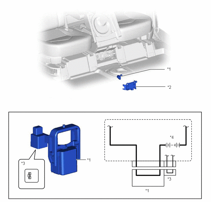
| *1 | Service Plug Grip | *2 | Service Plug Cover |
| *3 | Interlock Switch | *4 | HV Battery |