Home › Engine / Hybrid System › 2GR-FKS (ENGINE CONTROL) › SFI SYSTEM › 2020.02–2020.11
NM37A0E _51 Engine / Hybrid System _086659 2GR-FKS ENGINE CONTROL _0419212 SFI SYSTEM CO CONTROL F

2GR-FKS ENGINE CONTROL  SFI SYSTEM  CONTROL  DRIVE START CONTROL  


FUNCTION


a.

When abnormal driver accelerator pedal and shift operations are detected, the system restricts the engine output and informs the driver.
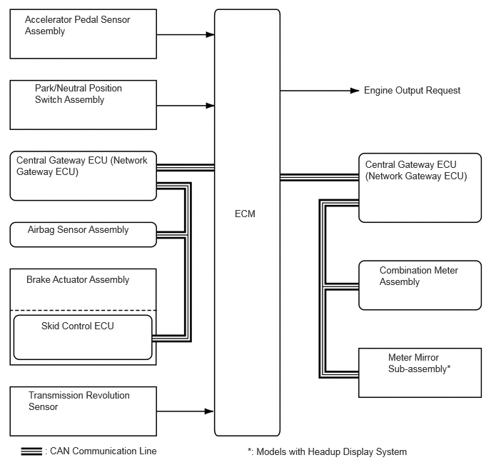
W145187E01
3.427,3.031 3.885,3.229 0.458,0.198 10 false ECM 0.365,0.198 1.969,0.615 1.604,0.417 10 false Accelerator Pedal Sensor Assembly 0.51,1.198 1.865,1.656 1.354,0.458 10 false Park/Neutral Position Switch Assembly 0.24,2.25 2.219,2.698 1.979,0.448 10 false Central Gateway ECU (Network Gateway ECU) 0.406,3.26 2.031,3.552 1.625,0.292 10 false Airbag Sensor Assembly 0.385,3.99 2,4.219 1.615,0.229 10 false Brake Actuator Assembly 0.604,4.667 1.771,4.875 1.167,0.208 10 false Skid Control ECU 0.417,5.677 1.938,6.115 1.521,0.438 10 false Transmission Revolution Sensor 0.656,6.49 2.427,6.719 1.771,0.229 10 false : CAN Communication Line 5.313,1.229 6.813,1.458 1.5,0.229 10 false Engine Output Request 5.333,2.313 6.906,2.875 1.573,0.563 10 false Central Gateway ECU (Network Gateway ECU) 5.542,3.854 6.76,4.313 1.219,0.458 10 false Combination Meter Assembly 5.667,5.125 6.677,5.688 1.01,0.563 10 false Meter Mirror Sub-assembly* 3.615,6.5 6.115,6.729 2.5,0.229 10 false *: Models with Headup Display System

HINT:
·

When the system is operating, even if the driver depresses and holds the accelerator pedal, engine output may increase on an uphill slope and decrease on a downhill slope. This behavior allows the system to restrict the vehicle speed and acceleration below the predetermined limit on slopes and is not a malfunction.

·

When the VSC OFF switch is operated to turn the TRC off, the system does not operate.

·

When Multi-terrain Select is selected, the system does not operate.


b.

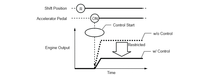
Control during Reverse Operation

i.

Responds to excessive depression of the accelerator pedal while operating in reverse.


ii.

Corrects engine output according to the road grade.

Control Start Conditions (When all of the following conditions are met, control starts.)
·

Shift position is R.

·

Accelerator pedal is depressed excessively.


Control Operation Restricts the engine output so the vehicle speed and acceleration are at or below a certain level.
Control Stop Conditions
·

Shift position is not R.

·

Accelerator pedal is fully released.


W110517E33
3.604,1.063 3.75,0.885 3.75,0.885 3.948,0.885 true 5.031,1.406 5.135,1.177 5.135,1.177 5.375,1.177 true 5.01,2.052 5.115,1.823 5.115,1.823 5.354,1.823 true 1.583,0.208 2.677,0.5 1.094,0.292 10 false Shift Position 1.302,0.573 2.49,0.927 1.188,0.354 10 false Accelerator Pedal 1.604,1.604 2.583,1.802 0.979,0.198 10 false Engine Output 3.802,2.49 4.198,2.708 0.396,0.219 10 false Time 4.542,1.5 5.281,1.698 0.74,0.198 10 false Restricted 5.438,1.104 6.219,1.302 0.781,0.198 10 false w/o Control 3.271,0.573 3.635,0.813 0.365,0.24 10 false ON 2.823,0.229 3.031,0.438 0.208,0.208 10 false R 4.01,0.802 4.969,1.115 0.958,0.313 10 false Control Start 5.417,1.729 6.198,1.927 0.781,0.198 10 false w/ Control


c.

Control during Manual Shift Operation

i.

Responds to shift operations with the accelerator pedal depressed.


ii.

Changes the limit amount according to the manual shift operation pattern.


iii.

Corrects engine output according to the road grade.

1.

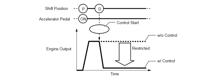
Control when Starting Off from a Parked Position

Control Start Conditions (When all of the following conditions are met, control starts.)
·

Shift position is changed from P to D/M, or P to R.

·

Accelerator opening angle is approximately 1/5 or higher.


Control Operation Restricts the engine output so the vehicle speed and acceleration are at or below a certain level.
Control Stop Conditions
·

Shift position is P or N.

·

Accelerator pedal is fully released.


W110518E32
3.615,0.927 3.792,0.771 3.792,0.771 3.99,0.771 true 5.021,1.427 5.146,1.219 5.146,1.219 5.396,1.219 true 5.021,2.323 5.146,2.115 5.146,2.115 5.396,2.115 true 1.563,0.208 2.51,0.542 0.948,0.333 10 false Shift Position 1.354,0.573 2.552,0.948 1.198,0.375 10 false Accelerator Pedal 2.844,0.229 3.073,0.458 0.229,0.229 10 false P 3.406,0.229 3.635,0.458 0.229,0.229 10 false D 2.781,0.573 3.104,0.823 0.323,0.25 10 false ON 4.042,0.698 4.896,1.01 0.854,0.313 10 false Control Start 1.604,1.604 2.563,1.969 0.958,0.365 10 false Engine Output 3.823,2.469 4.229,2.677 0.406,0.208 10 false Time 4.573,1.583 5.385,1.896 0.813,0.313 10 false Restricted 5.448,1.135 6.333,1.49 0.885,0.354 10 false w/o Control 5.448,2.021 6.24,2.406 0.792,0.385 10 false w/ Control

2.

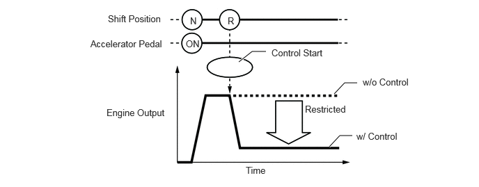
Control during Other Situations

Control Start Conditions (When all of the following conditions are met, control starts.)
·

Shift position is changed from R to D/M, D/M to R, or N to R.

·

Accelerator opening angle is approximately 1/5 or higher.


Control Operation Restricts the engine output so the vehicle speed and acceleration are at or below a certain level.
Control Stop Conditions
·

Shift position is P or N.

·

Accelerator pedal is fully released.


W110519E29
3.573,0.927 3.771,0.771 3.771,0.771 3.979,0.771 true 5,1.406 5.156,1.24 5.156,1.24 5.344,1.24 true 4.927,2.198 5.083,2.031 5.083,2.031 5.271,2.031 true 1.615,0.198 2.573,0.594 0.958,0.396 10 false Shift Position 1.354,0.573 2.5,0.958 1.146,0.385 10 false Accelerator Pedal 4.063,0.708 4.927,1.104 0.865,0.396 10 false Control Start 2.844,0.229 3.052,0.458 0.208,0.229 10 false N 3.406,0.229 3.615,0.458 0.208,0.229 10 false R 2.781,0.573 3.083,0.792 0.302,0.219 10 false ON 1.594,1.604 2.563,1.969 0.969,0.365 10 false Engine Output 3.677,2.469 4.229,2.792 0.552,0.323 10 false Time 4.563,1.552 5.26,1.792 0.698,0.24 10 false Restricted 5.427,1.146 6.24,1.552 0.813,0.406 10 false w/o Control 5.333,1.958 6.229,2.333 0.896,0.375 10 false w/ Control

HINT:
·

The engine output restraint level differs in the above 2 situations.

·

During control while a manual shift operation is performed (from control start until the accelerator pedal is released), the system informs the driver of the control via the combination meter assembly and meter mirror sub-assembly*.

*: Models with headup display system