P810 HYBRID TRANSMISSION / TRANSAXLE HYBRID TRANSAXLE SYSTEM CONTROL SEQUENTIAL SHIFT
FUNCTION
The sequential shiftmatic system enables the driver to select an appropriate shift range among 6 stages of engine braking force by operating the shift lever. By controlling the engine, generator (MG1) and motor (MG2), this system improves the generation response of the engine braking force. In addition, the engine speed is controlled to maintain high speeds, enhancing acceleration response when the driver depresses the accelerator pedal.
By moving the shift lever to S, the automatic shifting mode will be switched to shift range selecting mode. By operating the shift lever, driving in the shift range selected by the driver is possible, and the accelerator pedal characteristics and acceleration response can be selected.
In shift range selecting mode, when low shift range is selected, the engine braking force becomes greater during deceleration and the motive force between the accelerator intermediate and fully open range becomes greater during acceleration.
| Shift Range | Characteristics |
|---|---|
| Low Shift Range | Change in the driving force output between when the accelerator pedal is intermediately depressed and the fully depressed position is increased, improving the vehicle response to the driver's pedal operation. |
| High Shift Range | Change in the driving force output in accordance with changes in the accelerator pedal depression amount is decreased more than normal, enhancing accelerator control and making it easy to maintain the vehicle speed during constant-speed cruising. |
- HINT:
-
The sequential shiftmatic system does not indicate that maximum vehicle speed and maximum motion performance have been improved. Also, when the shift lever is moved to S, accelerator characteristics in drive mode (SPORT and ECO) are disabled.
An S mode position signal is output from the transmission control switch to the hybrid vehicle control ECU when the shift lever is moved from D to S. Then, the system switches to shift range selecting mode in order to enable shift range switching operation using the shift lever.
In shift range selecting mode, by performing a "+" (upshift) or "-" (downshift) operation using the shift lever, a shift-up signal or shift-down signal is output from the transmission control switch to the hybrid vehicle control ECU, and the shift range is changed. While using the selected shift range as the upper limit, an optimal shift point is automatically selected in accordance with driving conditions.
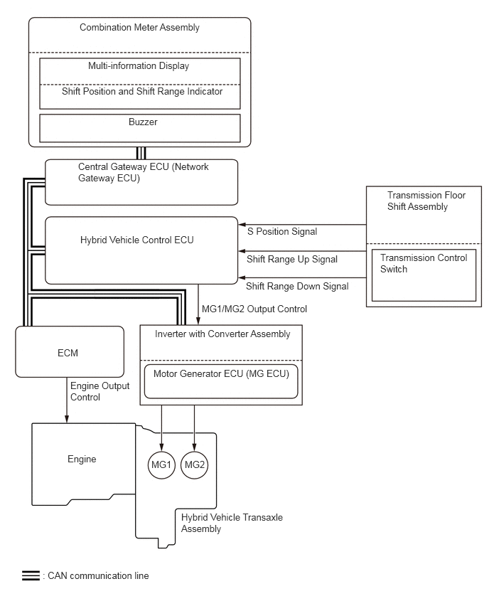
Holding the shift lever to "+" (upshift) in S will change the shift range to the S6 range regardless of the current shift range (S1 to S5).
In order to protect the transaxle, when accelerating while any range between the S1 range and the S4 range is selected in shift range selecting mode, sequential upshifts are automatically performed up to the S5 range by exceeding a predetermined vehicle speed in each shift range.
Limitations Regarding The Sequential Shiftmatic System
Upon receiving a downshifting request issued by the driver through the operation of the shift lever, this system limits the changing of the shift range if the vehicle speed exceeds the limit speed, and informs the driver by sounding the buzzer in the combination meter assembly.
| Downshift Request | Limit Speed (Reference Value) |
|---|---|
| 6 → 5 | - |
| 5 → 4 | 159 km/h (99 mph) |
| 4 → 3 | 129 km/h (80 mph) |
| 3 → 2 | 86 km/h (53 mph) |
| 2 → 1 | 54 km/h (34 mph) |