TRANSFER / 4WD / AWD DYNAMIC TORQUE VECTORING AWD SYSTEM DETAILS DIFFERENTIAL
CONSTRUCTION
FD15EF Type Rear Differential
A disconnect mechanism is used in the differential. When current flows to the dog clutch solenoid, the mechanism switches between connected and disconnected.
The electro magnetic control coupling sub-assembly distributes drive force between the left and right sides.
A large diameter unit ball bearing is used in the support portion of the ring gear. This allows the disconnect mechanism to be placed inside the ring gear, achieving size and weight reductions.
The gear ratio of the rear differential is set lower than that of the transfer. As a result, even though the rotation difference is absorbed by the coupling, the speed of the input side (before coupling) is set higher than the speed of the output side (after coupling), helping reduce driveline backlash and improve torque response.
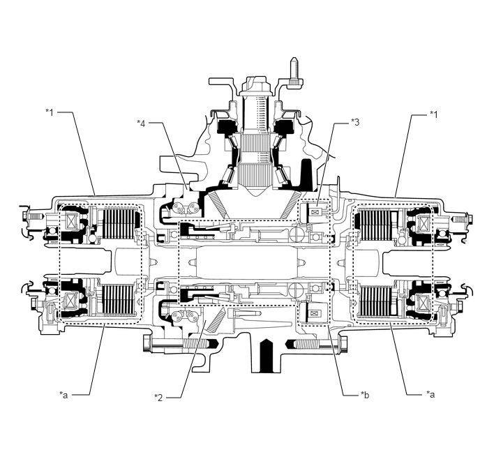
| *1 | Electro Magnetic Control Coupling Sub-Assembly | *2 | Differential Ring Gear |
| *3 | Rear Dog Clutch Solenoid | *4 | Ball Bearing |
| *a | Electromagnetic Control Coupling Portion | *b | Disconnect Mechanism Portion |
OPERATION
Differential Power Flow
The illustration below shows the flow of power from the propeller shaft:
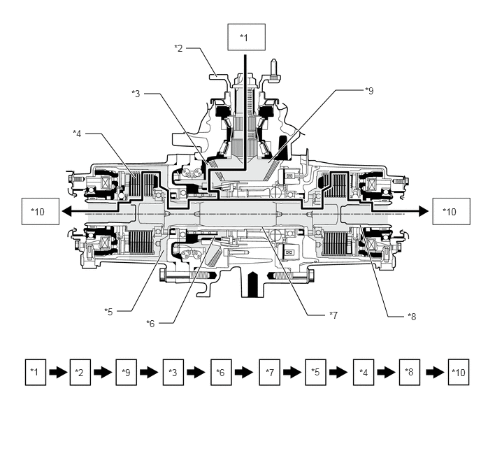
| *1 | Propeller Shaft | *2 | Companion Flange |
| *3 | Differential Ring Gear | *4 | Main Clutch |
| *5 | Coupling Housing | *6 | Clutch Sleeve |
| *7 | Differential Disconnect Shaft | *8 | Coupling Inner Hub |
| *9 | Differential Drive Pinion | *10 | Rear Drive Shaft |

|
Power Flow | - | - |