TRANSFER / 4WD / AWD DYNAMIC TORQUE VECTORING AWD SYSTEM DETAILS DISCONNECT MECHANISM
CONSTRUCTION
Transfer
The transfer disconnect mechanism is composed of a front dog clutch solenoid, cams, balls, a holder, a piston and a clutch sleeve.
A dog clutch is used for the clutch structure. The drag torque is reduced when disconnected to help increase fuel efficiency.
When the dog clutch is engaged, the drive force from the transaxle is transmitted from the input shaft to the clutch sleeve, and then output from the ring gear to the propeller shaft.
- HINT:
-
The transfer assembly is a non-disassembly type part. If replacing, replace the entire transfer assembly. Refer to the Repair Manual for details.
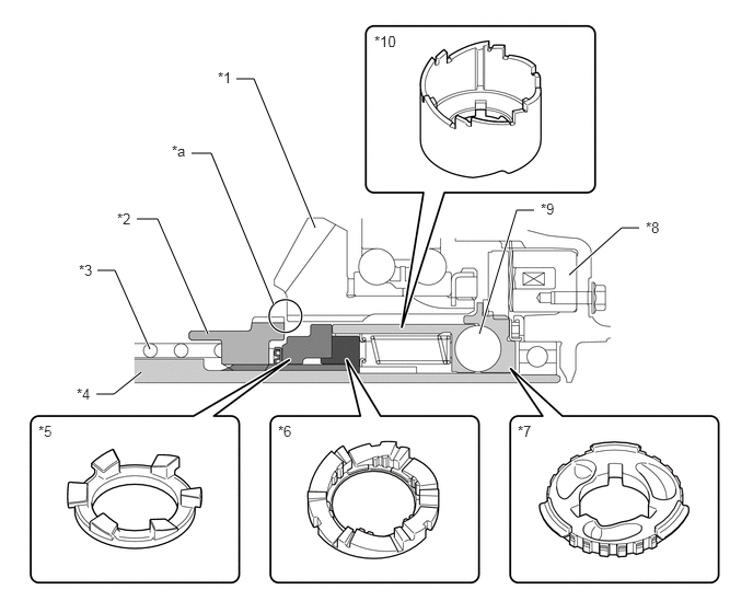
| *1 | Ring Gear | *2 | Clutch Sleeve |
| *3 | Return Spring | *4 | Input Shaft |
| *5 | Piston | *6 | Holder |
| *7 | Cam No. 2 | *8 | Front Dog Clutch Solenoid |
| *9 | Ball | *10 | Cam No. 1 |
| *a | Dog Clutch | - | - |
Differential
The differential disconnect mechanism is composed of a rear dog clutch solenoid, cams, balls, a piston, a holder and a clutch sleeve. A synchronizer mechanism is also used to synchronizes the rotations of the front and rear wheels.
A dog clutch is used for the clutch structure. The drag torque is reduced when disconnected to help increase fuel efficiency.
When the dog clutch is engaged, the drive force from the propeller shaft is transmitted to the differential ring gear, and then output from the clutch sleeve to the differential disconnect shaft.
- HINT:
-
The differential assembly is a non-disassembly type part. If replacing, replace the entire differential assembly. Refer to the Repair Manual for details.
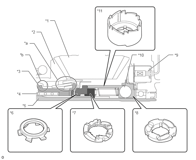
| *1 | Drive Pinion | *2 | Differential Ring Gear |
| *3 | Clutch Sleeve | *4 | Return Spring |
| *5 | Differential Disconnect Shaft | *6 | Piston |
| *7 | Holder | *8 | Cam No. 2 |
| *9 | Rear Dog Clutch Solenoid | *10 | Ball |
| *11 | Cam No. 1 | - | - |
| *a | Synchronizer Mechanism | *b | Dog Clutch |
OPERATION
Transfer
Disconnected to Connected
When drive current is output from the 4WD ECU assembly, the dog clutch solenoid attracts the armature, suppressing the rotation of the cam No. 2 attached to the armature and creating a rotational difference between the cam No. 2 and cam No. 1.
The rotational difference between the cam No. 2 and cam No. 1 causes the ball to expand the gap between the cam and piston. As a result, the cam No. 1 pushes up the piston in the holder together with the clutch sleeve.
When the drive current from the 4WD ECU assembly stops, the piston and clutch sleeve are pushed back due to the force of the return spring. At this time, the position of the piston returning to the holder becomes misaligned, increasing the amount that the piston and clutch sleeve return. As a result, the dog clutch attaches and the connection completes.
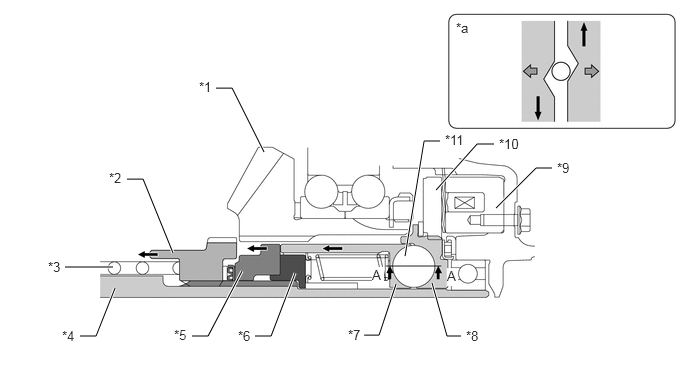
| *1 | Ring Gear | *2 | Clutch Sleeve |
| *3 | Return Spring | *4 | Input Shaft |
| *5 | Piston | *6 | Holder |
| *7 | Cam No. 1 | *8 | Cam No. 2 |
| *9 | Front Dog Clutch Solenoid | *10 | Armature |
| *11 | Ball | - | - |
| *a | A-A Cross Section | - | - |
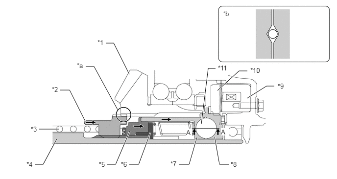
| *1 | Ring Gear | *2 | Clutch Sleeve |
| *3 | Return Spring | *4 | Input Shaft |
| *5 | Piston | *6 | Holder |
| *7 | Cam No. 1 | *8 | Cam No. 2 |
| *9 | Front Dog Clutch Solenoid | *10 | Armature |
| *11 | Ball | - | - |
| *a | Dog Clutch | *b | A-A Cross Section |
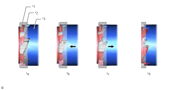
| *1 | Piston | *2 | Holder |
| *3 | Cam No. 1 | - | - |
| *a | Disconnected | *b | Solenoid ON |
| *c | Solenoid OFF | *d | Connected |
Connected to Disconnected
When drive current is output from the 4WD ECU assembly, the dog clutch solenoid attracts the armature, suppressing the rotation of the cam No. 2 attached to the armature and creating a rotational difference between the cam No. 2 and cam No. 1.
The rotational difference between the cam No. 2 and cam No. 1 causes the ball to expand the gap between the cam and piston. As a result, the cam No. 1 pushes up the piston in the holder together with the clutch sleeve, detaching the dog clutch.
When the drive current from the 4WD ECU assembly stops, the piston and clutch sleeve are pushed back due to the force of the return spring. At this time, the position of the piston returning to the holder becomes misaligned, keeping the dog clutch detached and completing the disconnection.
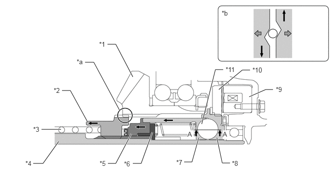
| *1 | Ring Gear | *2 | Clutch Sleeve |
| *3 | Return Spring | *4 | Input Shaft |
| *5 | Piston | *6 | Holder |
| *7 | Cam No. 1 | *8 | Cam No. 2 |
| *9 | Front Dog Clutch Solenoid | *10 | Armature |
| *11 | Ball | - | - |
| *a | Dog Clutch | *b | A-A Cross Section |
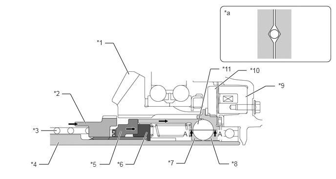
| *1 | Ring Gear | *2 | Clutch Sleeve |
| *3 | Return Spring | *4 | Input Shaft |
| *5 | Piston | *6 | Holder |
| *7 | Cam No. 1 | *8 | Cam No. 2 |
| *9 | Front Dog Clutch Solenoid | *10 | Armature |
| *11 | Ball | - | - |
| *a | A-A Cross Section | - | - |
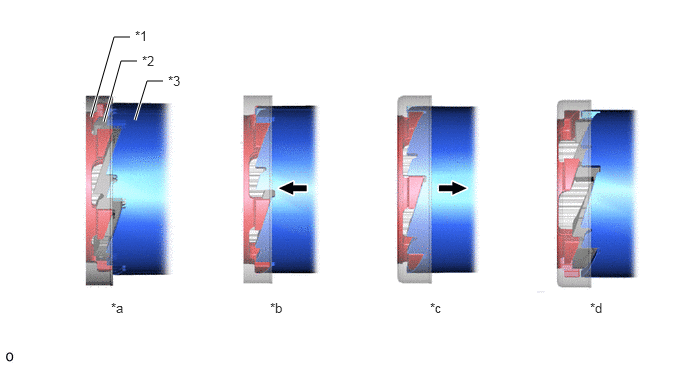
| *1 | Piston | *2 | Holder |
| *3 | Cam No. 1 | - | - |
| *a | Connected | *b | Solenoid ON |
| *c | Solenoid OFF | *d | Disconnected |
Differential
Disconnected to Connected
When drive current is output from the 4WD ECU assembly, the dog clutch solenoid attracts the armature, suppressing the rotation of the cam No. 2 attached to the armature and creating a rotational difference between the cam No. 2 and cam No. 1.
The rotational difference between the cam No. 2 and cam No. 1 causes the ball to expand the gap between the cam and piston. As a result, the cam No. 1 pushes up the piston in the holder together with the clutch sleeve. At this time, the synchronizer mechanism synchronizes the rotations of the differential ring gear and differential disconnect shaft, supporting the attachment of the dog clutch.
When the drive current from the 4WD ECU assembly stops, the piston and clutch sleeve are pushed back due to the force of the return spring. At this time, the position of the piston returning to the holder becomes misaligned, increasing the amount that the piston and clutch sleeve return. As a result, the dog clutch attaches and the connection completes.
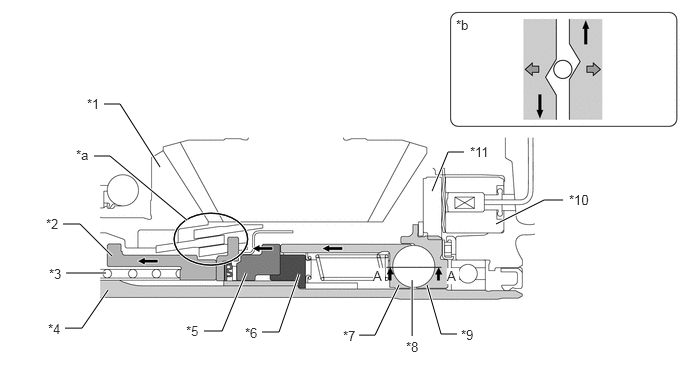
| *1 | Differential Ring Gear | *2 | Clutch Sleeve |
| *3 | Return Spring | *4 | Differential Disconnect Shaft |
| *5 | Piston | *6 | Holder |
| *7 | Cam No. 1 | *8 | Ball |
| *9 | Cam No. 2 | *10 | Rear Dog Clutch Solenoid |
| *11 | Armature | - | - |
| *a | Synchronizer Mechanism | *b | A-A Cross Section |
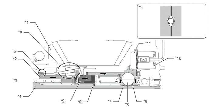
| *1 | Differential Ring Gear | *2 | Clutch Sleeve |
| *3 | Return Spring | *4 | Differential Disconnect Shaft |
| *5 | Piston | *6 | Holder |
| *7 | Cam No. 1 | *8 | Ball |
| *9 | Cam No. 2 | *10 | Rear Dog Clutch Solenoid |
| *11 | Armature | - | - |
| *a | Synchronizer Mechanism | *b | Dog Clutch |
| *c | A-A Cross Section | - | - |
| *1 | Piston | *2 | Holder |
| *3 | Cam No. 1 | - | - |
| *a | Disconnected | *b | Solenoid ON |
| *c | Solenoid OFF | *d | Connected |
Connected to Disconnected
When drive current is output from the 4WD ECU assembly, the dog clutch solenoid attracts the armature, suppressing the rotation of the cam No. 2 attached to the armature and creating a rotational difference between the cam No. 2 and cam No. 1.
The rotational difference between the cam No. 2 and cam No. 1 causes the ball to expand the gap between the cam No. 1 and cam No. 2. As a result, the cam No. 1 pushes up the piston in the holder together with the clutch sleeve, detaching the dog clutch.
When the drive current from the 4WD ECU assembly stops, the piston and clutch sleeve are pushed back due to the force of the return spring. At this time, the position of the piston returning to the holder becomes misaligned, keeping the dog clutch detached and completing the disconnection.
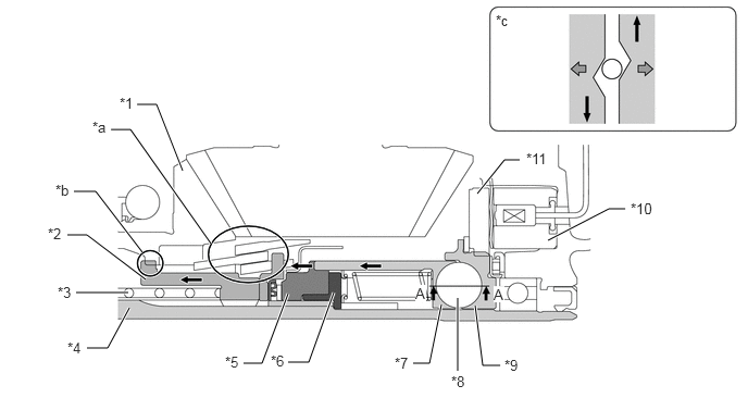
| *1 | Differential Ring Gear | *2 | Clutch Sleeve |
| *3 | Return Spring | *4 | Differential Disconnect Shaft |
| *5 | Piston | *6 | Holder |
| *7 | Cam No. 1 | *8 | Ball |
| *9 | Cam No. 2 | *10 | Rear Dog Clutch Solenoid |
| *11 | Armature | - | - |
| *a | Synchronizer Mechanism | *b | Dog Clutch |
| *c | A-A Cross Section | - | - |
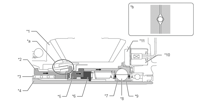
| *1 | Differential Ring Gear | *2 | Clutch Sleeve |
| *3 | Return Spring | *4 | Differential Disconnect Shaft |
| *5 | Piston | *6 | Holder |
| *7 | Cam No. 1 | *8 | Ball |
| *9 | Cam No. 2 | *10 | Rear Dog Clutch Solenoid |
| *11 | Armature | - | - |
| *a | Synchronizer Mechanism | *b | A-A Cross Section |
| *1 | Piston | *2 | Holder |
| *3 | Cam No. 1 | - | - |
| *a | Connected | *b | Solenoid ON |
| *c | Solenoid OFF | *d | Disconnected |