NM37A0E
_52
Drivetrain
_086682
AXLE AND DIFFERENTIAL
_0419693
DIFFERENTIAL SYSTEM
DE
DETAILS
F
AXLE AND DIFFERENTIAL DIFFERENTIAL SYSTEM DETAILS REAR DIFFERENTIAL
CONSTRUCTION
a.
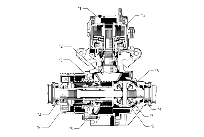
FD15ED Type Rear Differential
i.
The electro magnetic control coupling sub-assembly is placed in front of the rear differential.
ii.
A large diameter unit ball bearing is used in the support portion of the differential ring gear. This allows the disconnect mechanism to be placed inside the differential ring gear, achieving size and weight reductions.
4.417,0.885 4.74,0.552
4.74,0.552 4.896,0.552
true
2.906,0.292 3.063,0.292
3.063,0.292 3.417,0.594
true
2.594,4.521 2.781,4.521
2.781,4.521 3.344,3.844
true
4.594,3.479 5.063,4.094
5.063,4.094 5.219,4.094
true
4.49,3.625 5.094,4.448
5.094,4.448 5.25,4.448
true
4.698,2.99 5.25,2.49
5.25,2.49 5.406,2.49
true
2.229,2.104 2.458,2.104
2.458,2.104 3.094,2.688
true
1.479,4.5 1.708,4.5
1.708,4.5 2.083,3.979
true
1.479,4.042 1.708,4.042
1.708,4.042 2.219,3.302
true
4.906,3.313 5.333,3.854
5.333,3.854 5.49,3.854
true
2.25,1.625 2.479,1.625
2.479,1.625 3.604,2.625
true
2.427,4.448 2.74,4.604
0.313,0.156
10
false
*5
5.281,4.354 5.594,4.51
0.313,0.156
10
false
*6
5.26,4 5.635,4.177
0.375,0.177
10
false
*7
5.448,2.406 5.76,2.563
0.313,0.156
10
false
*8
4.958,0.458 5.271,0.615
0.313,0.156
10
false
*a
2.729,0.208 3.042,0.365
0.313,0.156
10
false
*1
2.063,2.031 2.375,2.188
0.313,0.156
10
false
*3
1.292,4.417 1.604,4.573
0.313,0.156
10
false
*b
2.073,1.542 2.385,1.698
0.313,0.156
10
false
*2
1.323,3.958 1.635,4.115
0.313,0.156
10
false
*4
5.542,3.76 5.854,3.917
0.313,0.156
10
false
*4
| *1 | Electro Magnetic Control Coupling Sub-assembly | *2 | Rear Drive Pinion |
| *3 | Ball Bearing | *4 | Rear Drive Shaft |
| *5 | Differential Ring Gear | *6 | Pinion Gear |
| *7 | Side Gear | *8 | Rear Differential Case |
| *a | Electromagnetic Control Coupling Portion | *b | Disconnect Mechanism Portion |
b.
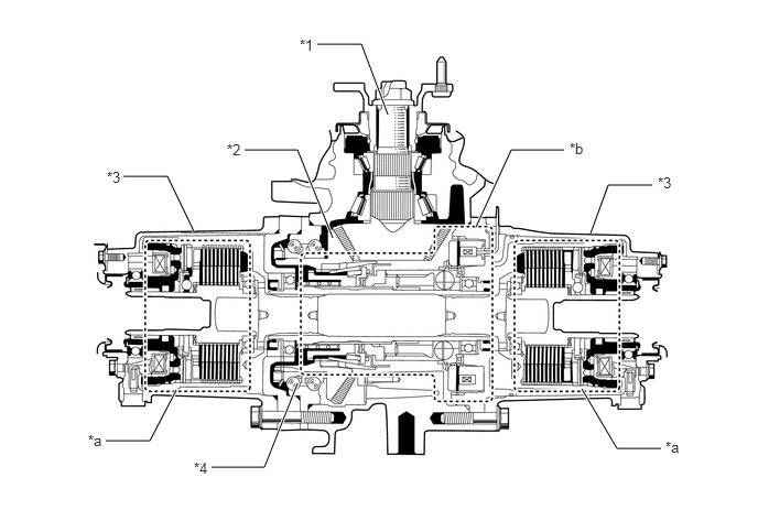
FD15EF Type Rear Differential
i.
The electro magnetic control coupling sub-assembly is placed to the left and right of the rear differential.
ii.
A large diameter unit ball bearing is used in the support portion of the differential ring gear. This allows the disconnect mechanism to be placed inside the differential ring gear, achieving size and weight reductions.
5.583,2.208 5.75,1.75
5.75,1.75 6.167,1.75
true
3.667,1.083 3.417,0.417
3.417,0.417 3,0.417
true
3.146,2.25 2.813,1.417
2.813,1.417 2.313,1.417
true
1.833,2.188 1.583,1.667
1.583,1.667 1.167,1.667
true
1.667,3.688 1.417,4.167
1.417,4.167 1,4.167
true
5.5,3.677 5.833,4.24
5.833,4.24 6.25,4.24
true
2.813,3.625 2.5,4.417
2.5,4.417 2,4.417
true
4.5,2.146 4.833,1.417
4.833,1.417 5.333,1.417
true
2.833,0.344 3.24,0.646
0.406,0.302
10
false
*1
2.146,1.333 2.552,1.635
0.406,0.302
10
false
*2
1.01,1.594 1.417,1.896
0.406,0.302
10
false
*3
0.833,4.083 1.24,4.385
0.406,0.302
10
false
*a
1.833,4.344 2.24,4.646
0.406,0.302
10
false
*4
6.292,4.146 6.698,4.396
0.406,0.25
10
false
*a
6.219,1.646 6.625,1.948
0.406,0.302
10
false
*3
5.385,1.323 5.792,1.625
0.406,0.302
10
false
*b
| *1 | Rear Drive Pinion | *2 | Differential Ring Gear |
| *3 | Electro Magnetic Control Coupling Sub-assembly | *4 | Ball Bearing |
| *a | Electromagnetic Control Coupling Portion | *b | Disconnect Mechanism Portion |