RM37A0E
_51
Engine / Hybrid System
_086853
2GR-FKS EMISSION CONTROL
_0416579
PURGE VALVE
A
2GR-FKS EMISSION CONTROL PURGE VALVE INSTALLATION
PROCEDURE

 25860
1.INSTALL PURGE VALVE (PURGE VSV)
a.
0.635,0.583 0.781,0.583
0.781,0.583 0.854,0.76
true
1.219,0.948 1.438,0.188
1.438,0.188 1.625,0.188
true
0.344,0.51 0.552,0.688
0.208,0.177
10
true
*1
1.75,0.083 1.938,0.292
0.188,0.208
10
true
*2
2,1.125 2.167,1.344
0.167,0.219
10
true
*b
2.104,0.917 2.323,1.125
0.219,0.208
10
false
*c
2.698,0.427 2.927,0.625
0.229,0.198
10
false
*a
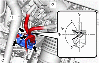
| *1 | No. 1 Fuel Vapor Feed Hose |
| *2 | Fuel Vapor Feed Hose |
| *a | RH Side |
| *b | Front |
| *c | 120° |
Install the purge valve (purge VSV) to the intake air surge tank assembly with the bolt.
- Torque:
- 21 N*m (214 kgf*cm, 15 ft.*lbf)
b.
Connect the No. 1 fuel vapor feed hose to the purge valve (purge VSV).
c.
Connect the fuel vapor feed hose to the purge valve (purge VSV) and slide the clip to secure it.
- HINT:
-
Engage the clip within the area shown in the illustration.
d.
Connect the purge valve (purge VSV) connector.
11209
2.INSTALL V-BANK COVER SUB-ASSEMBLY