MAINTENANCE AIR CONDITIONING FILTER INSTALLATION
PROCEDURE

 87139C
1.INSTALL CLEAN AIR FILTER
Engage the 2 guides on the cutout side of the air filter case and then engage the 2 guides as shown in the illustration to install the clean air filter.
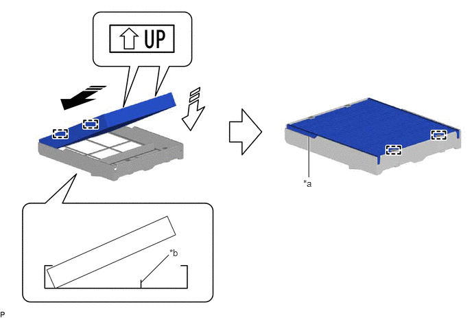
| *a | Cutout | *b | Rib |

|
Install in this Direction (1) | 
|
Install in this Direction (2) |
- NOTICE:
- ·
Make sure that the "UP" marks are facing the correct direction before installing the clean air filter.
·Make sure that there is no clearance between the clean air filter and air filter case and that the clean air filter is not deformed.
|
|
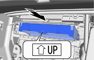
Install in this Direction |
Install the air filter sub-assembly as shown in the illustration.
- NOTICE:
-
Make sure that the "UP" mark is facing the correct direction before installing the air filter sub-assembly.
88899M
2.INSTALL AIR FILTER COVER PLATE
|
|
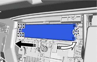
Install in this Direction (1) |
|
|
Install in this Direction (2) |
Engage the 2 guides and claw as shown in the illustration to install the air filter cover plate.
55501A
3.INSTALL GLOVE COMPARTMENT DOOR SUB-ASSEMBLY
Hold the glove compartment door assembly at an angle approximately 75° from its closed position and engage the 2 hinges horizontally as shown in the illustration.
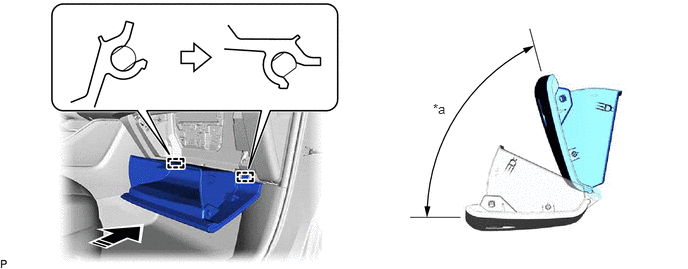
| *a | 75° | - | - |
|
|
Install in this Direction | - | - |
- NOTICE:
-
Engaging the hinges from an upward angle will deform the hinges. Be sure to install the glove compartment door assembly horizontally.
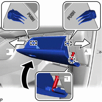
| *1 | Glove Compartment Door Stopper Sub-assembly |
Slightly bend the stoppers (A) and (B) in the directions indicated by the arrows shown in the illustration and engage the stoppers to install the glove compartment door assembly.
Engage the claw to connect the glove compartment door stopper sub-assembly.