RM37A0E
_51
Engine / Hybrid System
_086858
CRUISE CONTROL
_0417901
CRUISE CONTROL SYSTEM(for Gasoline Model)
U
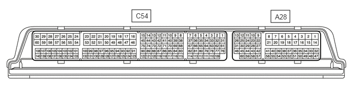
CRUISE CONTROL CRUISE CONTROL SYSTEM(for Gasoline Model) TERMINALS OF ECM
CHECK ECM
2.677,0.198 3.063,0.448
0.385,0.25
5.5,0.208 5.885,0.458
0.385,0.25
2.76,0.24 3.219,0.438
0.458,0.198
10
false
C54
5.583,0.26 6.042,0.458
0.458,0.198
10
false
A28
- HINT:
-
As a waterproof connector is used for the ECM, voltage, resistance and waveform inspections cannot be performed. The voltage, resistance and waveform values are provided for reference only.
a.
Measure the voltage and resistance according to the value(s) in the table below.
| Terminal No. (Symbol) | Terminal Description | Condition | Specified Condition |
|---|---|---|---|
| A28-27 (STP) - C54-53 (E1) | Stop light switch assembly signal | Brake pedal depressed | 11 to 14 V |
| Brake pedal released | Below 1 V | ||
| A28-41 (CCS) - C54-53 (E1) | Steering pad switch circuit | Cruise control switch not pushed | 1 MΩ or higher |
| Cruise control main switch pushed | Below 2.5 Ω | ||
| CANCEL switch pushed | 228 to 252 Ω | ||
| +RES switch pushed | 599 to 661 Ω | ||
| -SET switch pushed | 1463 to 1617 Ω | ||
| A28-42 (ST1-) - C54-53 (E1) | Stop light switch assembly signal | Ignition switch ON, brake pedal depressed | Below 1 V |
| Ignition switch ON, brake pedal released | 11 to 14 V |