RM37A0E
_55
Steering
_086875
STEERING COLUMN
_0418168
STEERING COLUMN ASSEMBLY
A
STEERING COLUMN STEERING COLUMN ASSEMBLY DISASSEMBLY
CAUTION / NOTICE / HINT
- NOTICE:
-
Before replacing the steering lock actuator assembly, refer to Service Bulletin.
PROCEDURE

 45020B
1.REMOVE STEERING LOCK ACTUATOR ASSEMBLY
a.
Secure the steering column assembly in a vise between aluminum plates.
- NOTICE:
-
Do not overtighten the vise.
b.
1.833,0.417 1.104,0.417
false
0.802,0.333 1.167,0.563
0.365,0.229
10
false
SST
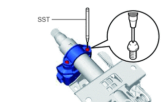
Using SST, strike a punch mark for drilling in the center of the steering lock set bolt.
- SST
- 09622-00010
- NOTICE:
-
When striking the punch mark, in order to prevent impact force from being applied to the steering lock actuator assembly, do not use a normal center punch.
c.
Using a drill, drill a hole in the 2 steering lock set bolts and insert a screw extractor.
d.
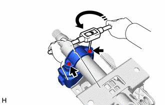
Using the screw extractor, remove the 2 steering lock set bolts, upper steering column clamp and steering lock actuator assembly.