CRUISE CONTROL LANE CONTROL SYSTEM TERMINALS OF ECU
CHECK FORWARD RECOGNITION CAMERA

- NOTICE:
- ·
DTCs may be output when connectors are disconnected during inspection. Therefore, be sure to clear the DTCs using the GTS once the inspection has been completed.
·Do not apply excessive force to the forward recognition camera connector.
Measure the voltage and resistance according to the value(s) in the table below.
| Terminal No. (Symbol) | Terminal Description | Condition | Specified Condition |
|---|---|---|---|
| R5-3 (LKSW) - R5-10 (GND) | Steering pad switch signal
(LTA/LDA main switch signal) |
Ignition switch off
LTA/LDA main switch off |
1 MΩ or higher |
| Ignition switch off
LTA/LDA main switch on |
228 to 252 Ω | ||
| R5-7 (IGB) - R5-10 (GND) | Power source | Ignition switch ON | 11 to 14 V |
| Ignition switch off | Below 1 V | ||
| R5-10 (GND) - Body ground | Ground | Always | Below 1 Ω |
Check for pulses according to the value(s) in the table below.
- HINT:
-
If the waveform is not similar to that shown in the illustration, a malfunction of a CAN bus line, terminating resistor, or the forward recognition camera is suspected.
| Terminal No. (Symbol) | Terminal Description | Condition | Specified Condition |
|---|---|---|---|
| R5-5 (CA1P) - R5-10 (GND) | CAN communication signal | Ignition switch ON | Pulse generation
(See waveform 1) |
| R5-6 (CANH) - R5-10 (GND) | CAN communication signal | Ignition switch ON | Pulse generation
(See waveform 1) |
| R5-11 (CA1N) - R5-10 (GND) | CAN communication signal | Ignition switch ON | Pulse generation
(See waveform 2) |
| R5-12 (CANL) - R5-10 (GND) | CAN communication signal | Ignition switch ON | Pulse generation
(See waveform 2) |
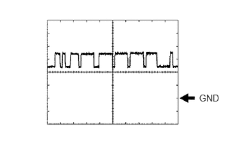
Waveform 1
| Item | Content |
|---|---|
| Tester Connection | ·
Between R5-5 (CA1P) and R5-10 (GND) ·
Between R5-6 (CANH) and R5-10 (GND) |
| Tool setting | 1 V/DIV., 10 μs./DIV. |
| Condition | Ignition switch ON |
- HINT:
-
The waveform varies depending on the CAN communication signal.
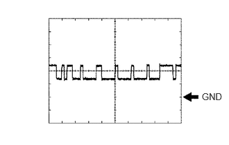
Waveform 2
| Item | Content |
|---|---|
| Tester Connection | ·
Between R5-11 (CA1N) and R5-10 (GND) ·
Between R5-12 (CANL) and R5-10 (GND) |
| Tool setting | 1 V/DIV., 10 μs./DIV. |
| Condition | Ignition switch ON |
- HINT:
-
The waveform varies depending on the CAN communication signal.