UA80F AUTOMATIC TRANSMISSION / TRANSAXLE AIR COOLED OIL COOLER INSTALLATION
PROCEDURE

 32913
1.INSTALL OIL COOLER BRACKET
- HINT:
-
Perform this procedure only when replacement of the oil cooler bracket is necessary.
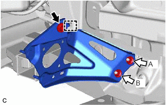

|
Bolt |

|
Nut |
Engage the guide and install the oil cooler bracket to the vehicle body with the bolt and 2 nuts.
- Torque:
- 6.0 N*m (61 kgf*cm, 53 in.*lbf)
- NOTICE:
-
When tightening the nuts (A and B), make sure not to lift the oil cooler bracket.
- HINT:
-
Tightening order: Temporarily tighten bolt → Fully tighten nut (A) → Fully tighten nut (B) → Fully tighten bolt
32971
2.INSTALL TRANSMISSION OIL THERMOSTAT
- HINT:
-
Perform this procedure only when replacement of the transmission oil thermostat is necessary.
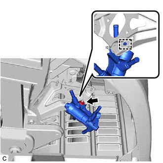
Engage the guide and install the transmission oil thermostat to the oil cooler bracket with the nut.
- Torque:
- 6.0 N*m (61 kgf*cm, 53 in.*lbf)
Install the oil cooler bracket to the transmission oil thermostat with the bolt.
- Torque:
- 6.0 N*m (61 kgf*cm, 53 in.*lbf)
Connect the No. 3 transmission oil cooler hose and outlet No. 1 oil cooler hose to the transmission oil thermostat and slide the 2 clips to secure them.
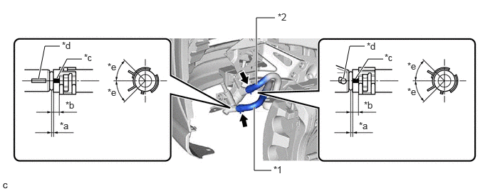
| *1 | No. 3 Transmission Oil Cooler Hose | *2 | Outlet No. 1 Oil Cooler Hose |
| *a | 0 to 3 mm (0 to 0.118 in.) | *b | 2 to 7 mm (0.0787 to 0.276 in.) |
| *c | Paint Mark | *d | Rib |
| *e | 45° (Claw of Clip Location) | - | - |
- NOTICE:
- ·
Make sure to slide the No. 3 transmission oil cooler hose and outlet No. 1 oil cooler hose until they contact the hose stopper of the transmission oil thermostat.
·Make sure to align the paint mark of the No. 3 transmission oil cooler hose and outlet No. 1 oil cooler hose with the rib of the transmission oil thermostat.
·Make sure that the claws of the clip are within the location shown in the illustration.
Install the No. 1 transmission oil cooler hose and No. 2 transmission oil cooler hose to the transmission oil thermostat and slide the 2 clips to secure them.
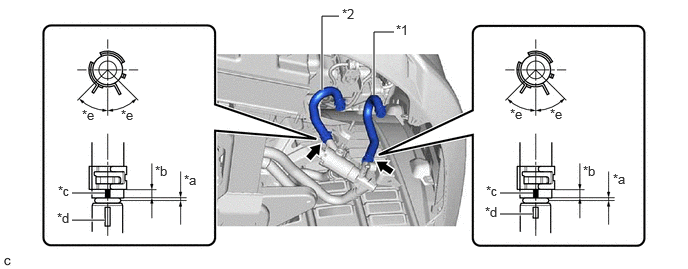
| *1 | No. 1 Transmission Oil Cooler Hose | *2 | No. 2 Transmission Oil Cooler Hose |
| *a | 0 to 3 mm (0 to 0.118 in.) | *b | 2 to 7 mm (0.0787 to 0.276 in.) |
| *c | Paint Mark | *d | Rib |
| *e | 45° (Claw of Clip Location) | - | - |
- NOTICE:
- ·
Make sure to slide the No. 1 transmission oil cooler hose and No. 2 transmission oil cooler hose until they contact the hose stopper of the transmission oil thermostat.
·Make sure to align the paint mark of the No. 1 transmission oil cooler hose and No. 2 transmission oil cooler hose with the rib of the transmission oil thermostat.
·Make sure that the claws of the clip are within the location shown in the illustration.
32910
3.INSTALL OIL COOLER ASSEMBLY
Install the oil cooler assembly to the oil cooler bracket with the 2 nuts and bolt.
- Torque:
- 6.0 N*m (61 kgf*cm, 53 in.*lbf)
4.CONNECT OIL COOLER HOSE
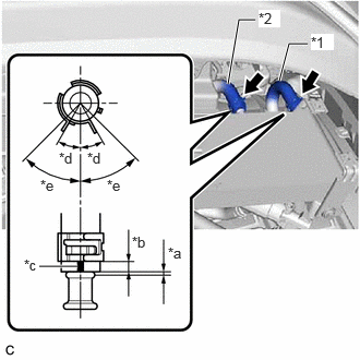
| *1 | No. 1 Transmission Oil Cooler Hose |
| *2 | No. 2 Transmission Oil Cooler Hose |
| *a | 0 to 3 mm (0 to 0.118 in.) |
| *b | 2 to 7 mm (0.0787 to 0.276 in.) |
| *c | Paint Mark (Front Side of Oil Cooler Assembly) |
| *d | 30° (Paint Mark Location) |
| *e | 45° (Claw of Clip Location) |
Connect the No. 1 transmission oil cooler hose and No. 2 transmission oil cooler hose to the oil cooler assembly and slide the 2 clips to secure them.
- NOTICE:
- ·
Make sure to slide the No. 1 transmission oil cooler hose and No. 2 transmission oil cooler hose until each contacts the hose stopper of the oil cooler assembly.
·Make sure that each paint mark and the claws of each clip are within the location shown in the illustration.
32917
5.INSTALL TRANSMISSION OIL COOLER AIR DUCT
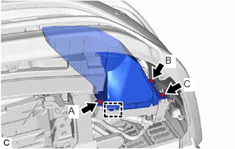
Engage the guide to temporarily install the transmission oil cooler air duct to the oil cooler assembly.
Install the transmission oil cooler air duct to the oil cooler assembly with the 3 bolts.
- Torque:
- 6.0 N*m (61 kgf*cm, 53 in.*lbf)
- HINT:
-
Tightening order: Bolt (A) → Bolt (B) → Bolt (C)
6.ADJUST AUTOMATIC TRANSAXLE FLUID
7.INSPECT FOR AUTOMATIC TRANSAXLE FLUID LEAK
53737B
8.INSTALL FRONT FENDER APRON SEAL LH
51444A
9.INSTALL REAR ENGINE UNDER COVER LH
51441
10.INSTALL NO. 1 ENGINE UNDER COVER
53852B
11.INSTALL FRONT WHEEL OPENING EXTENSION PAD LH
53851D
12.INSTALL FRONT WHEEL OPENING EXTENSION PAD RH