SEAT SEAT HEATER SYSTEM B14C1 Front Left Seat Heat Sensor Circuit
DESCRIPTION
Output to the front seat cushion heater temperature sensor stops if one of the following occurs: 1) the temperature sensor is open or shorted; or 2) the temperature sensor is damaged and its output value does not change.
| DTC No. | Detection Item | DTC Detection Condition | Trouble Area |
|---|---|---|---|
| B14C1 | Front Left Seat Heat Sensor Circuit | Seat heater temperature sensor malfunction | ·
Air conditioning amplifier assembly ·
Front seat cushion heater assembly LH ·
Wire harness or connector |
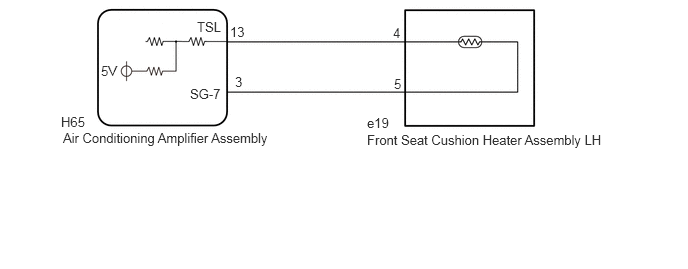
WIRING DIAGRAM
PROCEDURE
Clear the DTCs.
- Body Electrical > Air Conditioner > Clear DTCs
- 50002 121
- Result:
Proceed to NEXT
NEXT
Check for DTCs.
- Body Electrical > Air Conditioner > Trouble Codes
- 50001 121
- OK:
DTC B14C1 is not output.
- Result:
Proceed to OK NG
OK
Click hereGeneral>INTRODUCTION>HOW TO TROUBLESHOOT ECU CONTROLLED SYSTEMS>HOW TO PROCEED WITH TROUBLESHOOTING
NG
for Manual Seat: Click hereVehicle Interior>SEAT>FRONT SEAT CUSHION HEATER (for Manual Seat)>INSPECTION
for Power Seat: Click hereVehicle Interior>SEAT>FRONT SEAT CUSHION HEATER (for Power Seat)>INSPECTION
- Result:
Proceed to OK NG
OK
NG
for Manual Seat: Click hereVehicle Interior>SEAT>FRONT SEAT CUSHION HEATER (for Manual Seat)>REMOVAL
for Power Seat: Click hereVehicle Interior>SEAT>FRONT SEAT CUSHION HEATER (for Power Seat)>REMOVAL
Disconnect the H65 air conditioning amplifier assembly connector.
Measure the resistance according to the value(s) in the table below.
- Standard Resistance:
Tester Connection Condition Specified Condition H65-13 (TSL) - e19-4 Always Below 1 Ω H65-13 (TSL) or e19-4 - Body ground Always 10 kΩ or higher H65-3 (SG-7) - e19-5 Always Below 1 Ω H65-3 (SG-7) or e19-5 - Body ground Always 10 kΩ or higher
- Result:
Proceed to OK NG
OK
NG