BRAKE CONTROL / DYNAMIC CONTROL SYSTEMS BRAKE HOLD SWITCH INSPECTION
PROCEDURE

 84390B
1.INSPECT BRAKE HOLD SWITCH (ELECTRIC PARKING BRAKE SWITCH ASSEMBLY)
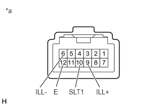
| *a | Component without harness connected
(Brake Hold Switch (Electric Parking Brake Switch Assembly)) |
Make sure that there is no looseness in the locking part and the connecting part of the connector.
- OK:
The connector is securely connected.
Disconnect the brake hold switch (electric parking brake switch assembly) connector.
Check both the connector case and the terminal for deformation and corrosion.
- OK:
No deformation or corrosion.
Measure the resistance according to the value(s) in the table below.
- Standard Resistance:
Tester Connection Condition Specified Condition 10 (SLT1) - 12 (E) Switch pushed Below 1 Ω 10 (SLT1) - 12 (E) Switch not pushed 10 kΩ or higher
Connect a positive (+) lead from the auxiliary battery to terminal 9 (ILL+) and a negative (-) lead to terminal 6 (ILL-) of the brake hold switch (electric parking brake switch assembly) connector.
- OK:
The brake hold switch (electric parking brake switch assembly) illumination illuminates.
If the result is not as specified, replace the brake hold switch (electric parking brake switch assembly).