RM37A0E
_54
Brake
_086868
BRAKE CONTROL / DYNAMIC CONTROL SYSTEMS
_0420940
DOWNHILL ASSIST CONTROL SWITCH
G
BRAKE CONTROL / DYNAMIC CONTROL SYSTEMS DOWNHILL ASSIST CONTROL SWITCH INSPECTION
PROCEDURE

 84988H
1.INSPECT DOWNHILL ASSIST CONTROL SWITCH
a.
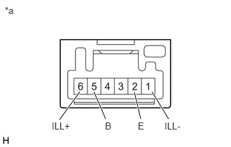
2.51,1.771 2.26,1.365
true
2.094,1.771 2,1.375
true
1.573,1.771 1.396,1.365
true
0.885,1.781 1.188,1.365
true
0.073,0.073 0.49,0.406
0.417,0.333
10
false
*a
1.563,1.792 1.927,2.01
0.365,0.219
10
false
B
2.052,1.792 2.323,2
0.271,0.208
10
false
E
2.448,1.792 2.823,2.021
0.375,0.229
10
false
ILL-
0.771,1.792 1.146,2.01
0.375,0.219
10
false
ILL+
| *a | Component without harness connected
(Downhill Assist Control Switch) |
Make sure that there is no looseness in the locking part and the connecting part of the connector.
- OK:
The connector is securely connected.
b.
Disconnect the downhill assist control switch connector.
c.
Check both the connector case and the terminal for deformation and corrosion.
- OK:
No deformation or corrosion.
d.
Measure the resistance according to the value(s) in the table below.
- Standard Resistance:
Tester Connection Condition Specified Condition 5 (B) - 2 (E) Switch pushed Below 1 Ω 5 (B) - 2 (E) Switch not pushed 10 kΩ or higher
e.
Connect a positive (+) lead from the battery to terminal 6 (ILL+) and a negative (-) lead to terminal 1 (ILL-) of the downhill assist control switch connector.
- OK:
The downhill assist control switch illumination illuminates.
If the result is not as specified, replace the downhill assist control switch.