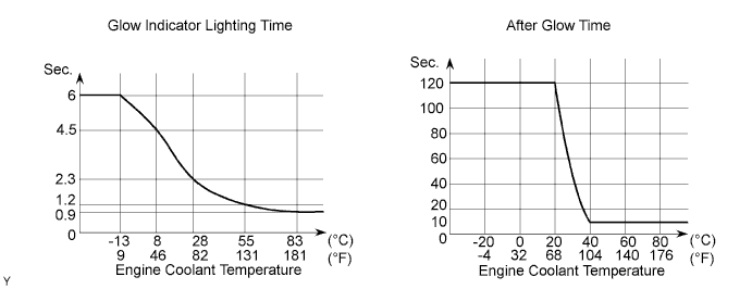
ECD SYSTEM > Pre-heating Control Circuit |
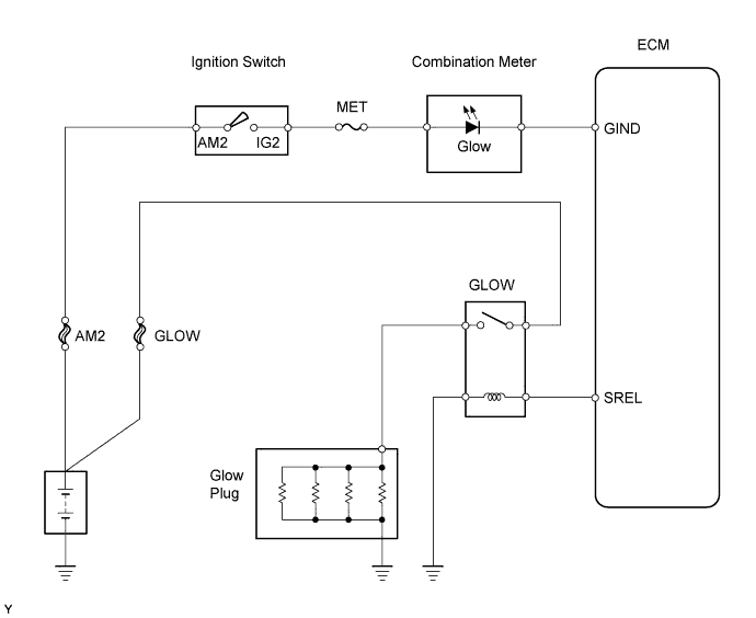
| 1.CHECK GLOW INDICATOR LIGHT |
Turn the ignition switch ON.
Check that the glow indicator light comes on.
|
| ||||
| OK | |
 |
| 2.CHECK GLOW PLUG (INSTALLATION) |
Check that the glow plug and glow plug wire are securely installed.
|
| ||||
| OK | |
|
| 3.INSPECT GLOW PLUG |
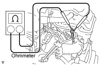 |
Measure the resistance of the glow plug.
|
| ||||
| OK | |
|
| 4.CHECK FOR INDICATOR LIGHTING TIME AND AFTER GLOW TIME |
|
| ||||
| OK | |
|
| 5.READ OUTPUT DTC |
Read the DTC (Click here).
| Result | Proceed to |
| DTC is not output | A |
| DTC is output | B |
|
| ||||
| A | |
|
| 6.INSPECT GLOW RELAY (Marking: GLOW) |
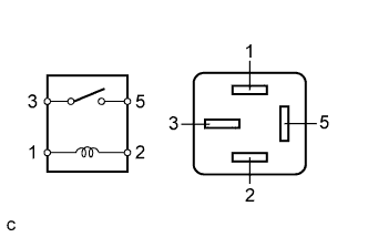 |
Measure the resistance of the glow relay.
| Tester Connection | Specified Condition |
| 3 - 5 | 10 kΩ or higher (No continuity) |
| 3 - 5 | Below 1 Ω (when battery voltage is applied to terminals 1 and 2) |
|
| ||||
| OK | |
|
| 7.CHECK ECM (SREL VOLTAGE) |
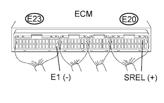 |
Turn the ignition switch to the START position.
Measure the voltage of the ECM connector.
| Tester Connection | Condition | Specified Condition |
| E20-2 (SREL) - E23-14 (E1) | Cranking | 9 to 14 V |
|
| ||||
| OK | |
|
| 8.CHECK WIRE HARNESS (GLOW RELAY [Marking: GLOW] - ECM AND BODY GROUND) |
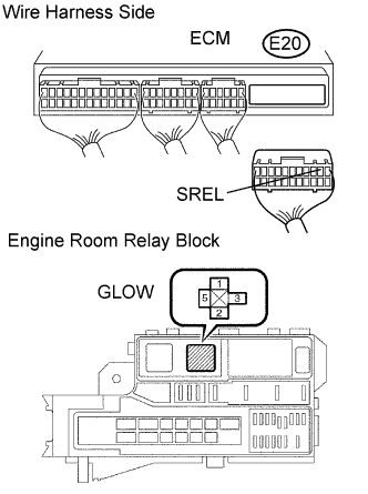 |
Disconnect the E20 ECM connector.
Disconnect the glow relay from the engine room relay block.
Measure the resistance of the wire harness side connectors.
| Tester Connection | Specified Condition |
| Relay block glow relay terminal 2 - E20-2 (SREL) | Below 1 Ω |
| Relay block glow relay terminal 1 - Body ground | Below 1 Ω |
| E20-2 (SREL) - Body ground | 10 kΩ or higher |
|
| ||||
| OK | |
|
| 9.CHECK WIRE HARNESS (GLOW RELAY [Marking: GLOW] - GLOW PLUG AND BATTERY) |
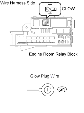 |
Disconnect the battery negative (-) cable.
Disconnect the battery positive (+) cable.
Remove the glow relay from the engine room relay block.
Disconnect the glow plug wire.
Measure the resistance of the wire harness side connectors.
| Tester Connection | Specified Condition |
| Relay block glow relay terminal 3 - Glow plug wire | Below 1 Ω |
| Relay block glow relay terminal 5 - Positive terminal of the battery | Below 1 Ω |
|
| ||||
| OK | ||
 | ||
| ||
| 10.CHECK ECM (GIND VOLTAGE) |
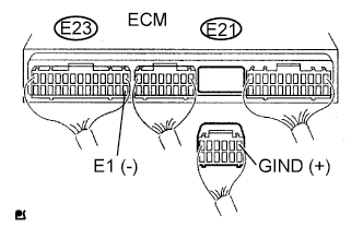 |
Disconnect the E21 ECM connector.
Turn the ignition switch ON.
Measure the voltage of the wire harness side connectors.
| Tester Connection | Specified Condition |
| E21-1 (GIND) - E23-14 (E1) | 9 to 14 V |
|
| ||||
| NG | |
|
| 11.CHECK WIRE HARNESS (ECM - COMBINATION METER) |
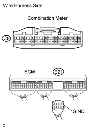 |
Disconnect the C8 combination meter connector.
Disconnect the E21 ECM connector.
Measure the resistance of the wire harness side connectors.
| Tester Connection | Specified Condition |
| C8-40 - E21-1 (GIND) | Below 1 Ω |
|
| ||||
| OK | |
|
| 12.CHECK FUSE (MET FUSE) |
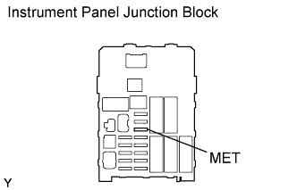 |
Remove the MET fuse from the instrument panel junction block.
Measure the resistance of the fuse.
| Tester Connection | Specified Condition |
| MET fuse | Below 1 Ω |
|
| ||||
| OK | |
|
| 13.CHECK WIRE HARNESS (COMBINATION METER - BATTERY) |
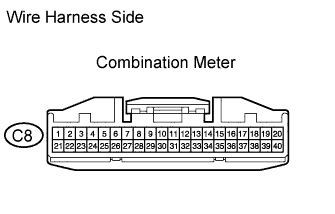 |
Disconnect the C8 combination meter connector.
Turn the ignition switch ON.
Measure the voltage of the wire harness side connector.
| Tester Connection | Specified Condition |
| C8-21 - Body ground | 9 to 14 V |
|
| ||||
| NG | ||
| ||
| ||

