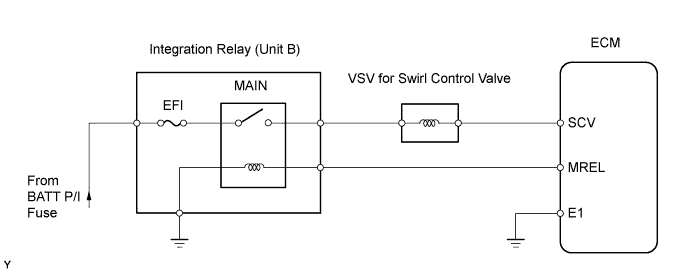
DTC P2008/58 Intake Manifold Runner Control Circuit / Open (Bank 1) |
| DTC No. | DTC Detection Condition | Trouble Area |
| P2008/58 | When actual intake air volume detected by MAF meter continues to be smaller than volume estimated from boost pressure and intake air temperature sensor, ECM determines that swirl control valve is stuck closed. (1 trip detection logic) |
|
| 1.CHECK OTHER DTC OUTPUT (IN ADDITION TO DTC P2008/58) |
Connect the intelligent tester to the DLC3.
Turn the ignition switch ON and turn the intelligent tester ON.
Enter the following menus: Powertrain / Engine / DTC.
Read the DTCs.
| Display (DTC Output) | Proceed to |
| P2008/58 | A |
| P2008/58 and other DTCs | B |
|
| ||||
| A | |
 |
| 2.CHECK CONNECTION OF VACUUM HOSE |
Check the vacuum hose connection of the swirl control valve system.
|
| ||||
| OK | |
|
| 3.INSPECT VACUUM SWITCHING VALVE FOR SWIRL CONTROL VALVE (OPERATION) |
|
| ||||
| OK | |
|
| 4.INSPECT VACUUM SWITCHING VALVE FOR SWIRL CONTROL VALVE (RESISTANCE) |
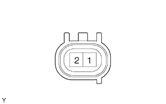 |
Disconnect the S9 VSV connector.
Measure the resistance of the VSV.
| Tester Connection | Condition | Specified Condition |
| 1 - 2 | 20°C (68°F) | 37 to 44 Ω |
|
| ||||
| OK | |
|
| 5.CHECK WIRE HARNESS (VACUUM SWITCHING VALVE FOR SWIRL CONTROL VALVE - ECM) |
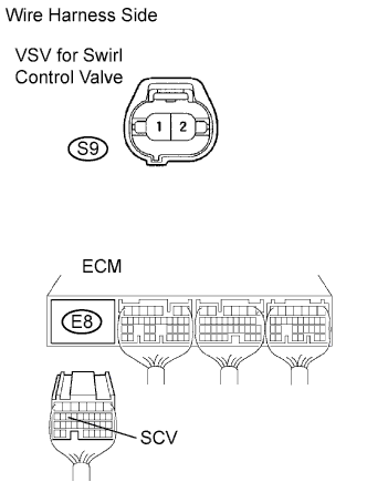 |
Disconnect the S9 VSV connector.
Disconnect the E8 ECM connector.
Measure the resistance of the wire harness side connectors.
| Tester Connection | Specified Condition |
| S9-1 - E8-15 (SCV) | Below 1 Ω |
| S9-1 or E8-15 (SCV) - Body ground | 10 kΩ or higher |
|
| ||||
| OK | |
|
| 6.CHECK WIRE HARNESS (INTEGRATION RELAY (MAIN RELAY) - VACUUM SWITCHING VALVE FOR SWIRL CONTROL VALVE) |
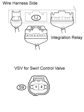 |
Remove the integration relay from the engine room junction block (Click here).
Disconnect the 1J integration relay connector.
Disconnect the S9 VSV connector.
Measure the resistance of the wire harness side connectors.
| Tester Connection | Specified Condition |
| 1J-5 - S9-2 | Below 1 Ω |
| 1J-5 or S9-2 - Body ground | 10 kΩ or higher |
|
| ||||
| OK | |
|
| 7.INSPECT INTAKE MANIFOLD (SWIRL CONTROL VALVE OPERATION) |
|
| ||||
| OK | |
|
| 8.CHECK EGR VALVE ASSEMBLY |
|
| ||||
| OK | |
|
| 9.INSPECT INTAKE AIR TEMPERATURE SENSOR |
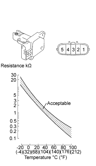 |
Remove the MAF meter.
Measure the resistance of the IAT sensor.
| Tester Connection | Condition | Specified Condition |
| 4 - 5 | -20°C (-4°F) | 13.6 to 18.4 kΩ |
| 4 - 5 | 20°C (68°F) | 2.21 to 2.69 kΩ |
| 4 - 5 | 60°C (140°F) | 0.49 to 0.67 kΩ |
|
| ||||
| OK | |
|
| 10.CHECK OTHER DTC OUTPUT (IN ADDITION TO DTC P2008/58) |
Connect the intelligent tester to the DLC3.
Turn the ignition switch ON and turn the intelligent tester ON.
Enter the following menus: Powertrain / Engine / DTC.
Read the DTCs.
| Display (DTC Output) | Proceed to |
| P2008/58 | A |
| No DTC | B |
|
| ||||
| A | ||
 | ||
| ||
