Home › SUSPENSION & AXLE › AXLE › REAR AXLE SHAFT

REAR AXLE SHAFT > INSTALLATION

for Preparation Click here


HINT:
  1. Use the same procedures for the RH and LH side.
  2. The procedures listed below are for the LH side.
  3. A bolt without a torque specification is shown in the standard bolt chart (Click here).


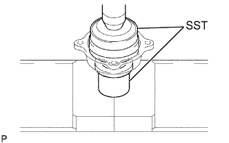
1. INSTALL REAR AXLE SHAFT BEARING


F049872E01
  1. Using SST and a press, press in a new bearing.

    SST
    09515-30010  
    09950-60020   (09951-00890)


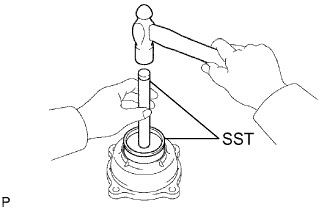
2. INSTALL REAR AXLE SHAFT OUTER OIL SEAL


F049873E01
  1. Using SST and a hammer, tap in a new oil seal.

    SST
    09950-60010   (09951-00610)
    09950-70010   (09951-07150)


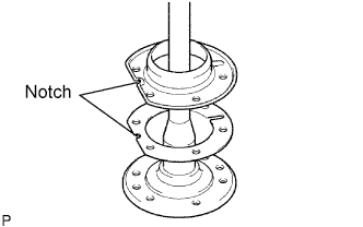
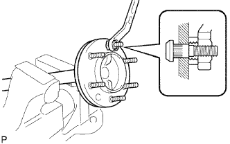
3. INSTALL REAR AXLE HUB BOLT


G020977E01
  1. Install a new deflector gasket and deflector to the axle shaft.
    HINT:
    Align the 2 notches.


    G020973E01
  1. Pass the bolts through the axle hub.

  1. Temporarily install a plate washer and nut to the bolt. Install the hub bolt by tightening the nut.

  1. Remove the nut and plate washer.


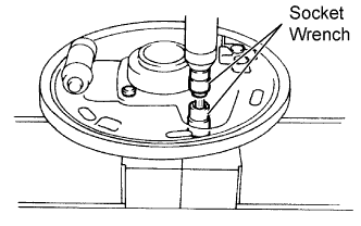
4. INSTALL BACKING PLATE


F050877E01
  1. Position the backing plate on the bearing case.

  1. Using 2 socket wrenches, press in the serration bolts.


5. INSTALL REAR AXLE SHAFT IN BACKING PLATE


F050878E01
  1. Coat a new oil seal lip with MP grease.

  1. Install the backing plate and bearing retainer on the rear axle shaft.

  1. Using SST and a press, press in the axle shaft into the backing plate.

    SST
    09316-60011   (09316-00051)

  1. Using a snap ring expander, install a new snap ring.


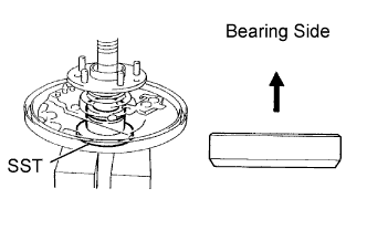
6. INSTALL REAR AXLE BEARING RETAINER AND ABS SPEED SENSOR ROTOR (w/ ABS)


F050879E02
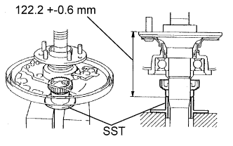
  1. Using SST and a press, press in a new sensor rotor and new bearing retainer to the axle shaft until length is within the standard range.

    SST
    09316-60011   (09316-00051)

    Standard length:
    122.2 +-0.6 mm (4.811 +-0.024 in.)

    NOTICE:
    Oil leakage may occur if length is not within the standard range and the lip of the oil seal does not contact to the retainer.


7. REMOVE REAR AXLE SHAFT OIL SEAL


F050775E01
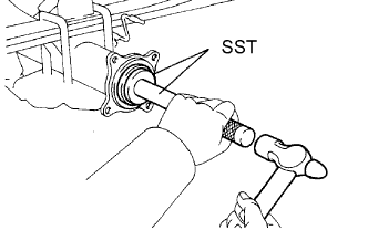
  1. Using SST and a hammer, tap in a new oil seal.

    SST
    09950-60020   (09951-00770)
    09950-70010   (09951-07150)

  1. Coat the lip of the oil seal with MP grease.


8. INSTALL REAR AXLE SHAFT WITH BACKING PLATE


F049869E01
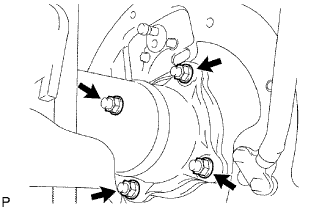
  1. Install a new O-ring.

  1. Install the axle shaft with the 4 nuts.

    Torque:
    43 N*m{ 438 kgf*cm , 32 ft.*lbf }


9. CONNECT BRAKE LINE AND PARKING BRAKE CABLE


F050208E01
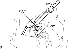
  1. Using SST, connect the brake tube.

    SST
    09023-00101  

    Torque:
    15 N*m{ 155 kgf*cm , 11 ft.*lbf }
    14 N*m{ 143 kgf*cm , 10 ft.*lbf } for use with SST

    HINT:
    Use a torque wrench with a fulcrum length of 30 cm (11.81 in.).

  1. Connect the parking brake cable with the 2 bolts.


10. INSTALL REAR BRAKE SHOE (for 2WD)
  1. Install the rear brake shoe (Click here).


11. INSTALL REAR BRAKE SHOE (for 4WD)
  1. Install the rear brake shoe (Click here).


12. INSTALL BRAKE DRUM


13. INSTALL SPEED SENSOR REAR LH (w/ ABS)


  1. Install the speed sensor RH with the bolt.
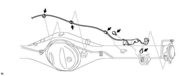

    C225641

    Torque:
    8.5 N*m{ 87 kgf*cm , 75 in.*lbf }

    NOTICE:
    1. Make sure there are no pieces of iron or other foreign matter attached to the sensor tip.
    2. While inserting the speed sensor into the axle housing hole, do not strike or damage the sensor tip.
    3. After installing the speed sensor, make sure there is no clearance or foreign matter between the sensor stay part and the axle housing.

  1. Install the harness clamp with the bolt.

    Torque:
    8.5 N*m{ 87 kgf*cm , 75 in.*lbf }

    NOTICE:
    1. When installing the clamp, do not twist the wire harness.
    2. Make sure the clamp rotation stopper touches the installation position.

  1. Attach the 3 clamps.

    NOTICE:
    When attaching the clamps, do not twist the wire harness.


  1. Install the speed sensor LH with the bolt.
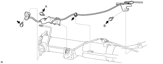

    C225640E01

    Torque:
    8.5 N*m{ 87 kgf*cm , 75 in.*lbf }

    NOTICE:
    1. Make sure there are no pieces of iron or other foreign matter attached to the sensor tip.
    2. While inserting the speed sensor into the axle housing hole, do not strike or damage the sensor tip.
    3. After installing the speed sensor, make sure there is no clearance or foreign matter between the sensor stay part and the axle housing.

  1. Install the 2 harness clamps with the 2 bolts.

    Torque:
    for bolt A:
    8.5 N*m{ 87 kgf*cm , 75 in.*lbf }
    for bolt B:
    32 N*m{ 326 kgf*cm , 24 ft.*lbf }

    NOTICE:
    1. When installing the clamps, do not twist the wire harness.
    2. Make sure the clamp rotation stopper touches the installation position.

  1. Attach the clamp.

    NOTICE:
    When attaching the clamp, do not twist the wire harness.

  1. Connect the sensor connector.

    NOTICE:
    1. Securely connect the connector.
    2. When connecting the connector, do not twist the wire harness.


14. BLEED AIR FROM BRAKE LINE
  1. TMT made LHD:
    Bleed air from the brake line (Click here).

  1. TMT made RHD:
    Bleed air from the brake line (Click here).

  1. TMT made LHD:
    Bleed air from the brake line .

  1. TMT made RHD:
    Bleed air from the brake line .


15. CHECK BRAKE FLUID LEVEL IN RESERVOIR
  1. TMT made LHD:
    Check the brake fluid level in the reservoir (Click here).

  1. TMT made RHD:
    Check the brake fluid level in the reservoir (Click here).

  1. TMT made LHD:
    Check the brake fluid level in the reservoir .

  1. TMT made RHD:
    Check the brake fluid level in the reservoir .


16. CHECK FOR BRAKE FLUID LEAKAGE


17. INSTALL REAR WHEEL

Torque:
152 N*m{ 1,550 kgf*cm , 112 ft.*lbf } for 2WD (steel type)
121 N*m{ 1,234 kgf*cm , 89 ft.*lbf } for 2WD (aluminum type)
105 N*m{ 1,071 kgf*cm , 77 ft.*lbf } for 4WD


18. INSPECT AND ADJUST PARKING BRAKE LEVER TRAVEL
  1. Inspect and adjust parking brake lever travel (Click here).


19. CHECK ABS SPEED SENSOR SIGNAL (w/ ABS)
  1. Check the ABS speed sensor signal (Click here).