REAR DIFFERENTIAL CARRIER ASSEMBLY (w/ Differential Lock) > DISASSEMBLY |
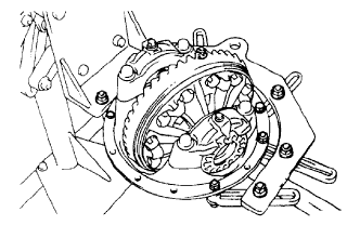
| 1. FIX REAR DIFFERENTIAL CARRIER ASSEMBLY |
|
| 2. INSPECT RUNOUT OF REAR DRIVE PINION COMPANION FLANGE SUB-ASSEMBLY REAR |
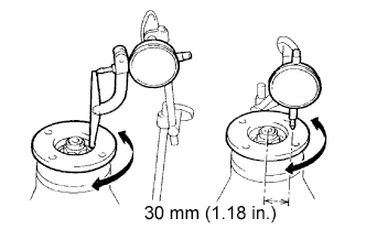 |
Using a dial indicator, measure the runout of the companion flange vertically and laterally.
| Runout | Maximum |
| Vertical runout | 0.10 mm (0.0039 in.) |
| Lateral runout | 0.10 mm (0.0039 in.) |
| 3. INSPECT RUNOUT OF DIFFERENTIAL RING GEAR |
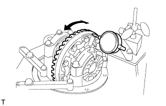 |
Using a dial indicator, measure the runout of the ring gear.
| 4. INSPECT DIFFERENTIAL RING GEAR BACKLASH |
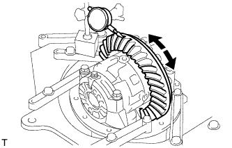 |
Using a dial indicator, measure the backlash of the ring gear.
| 5. INSPECT DIFFERENTIAL DRIVE PINION PRELOAD |
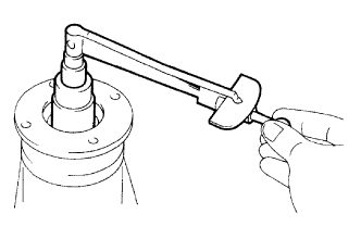 |
Using a torque wrench, measure the preload of backlash between the drive pinion and ring gear.
| 6. INSPECT TOTAL PRELOAD |
|
Using a torque wrench, measure the preload with the teeth of the drive pinion and ring gear in contact.
Using a torque wrench, measure the total preload.
| 7. REMOVE DIFFERENTIAL LOCK SHIFT ACTUATOR |
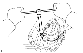 |
Remove the 4 bolts and actuator from the differential carrier.
Remove the O-ring.
| 8. REMOVE NO. 1 TRANSFER INDICATOR SWITCH |
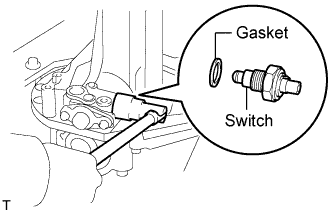 |
Remove the switch and gasket.
| 9. REMOVE REAR DIFFERENTIAL LOCK SHIFT FORK SHAFT |
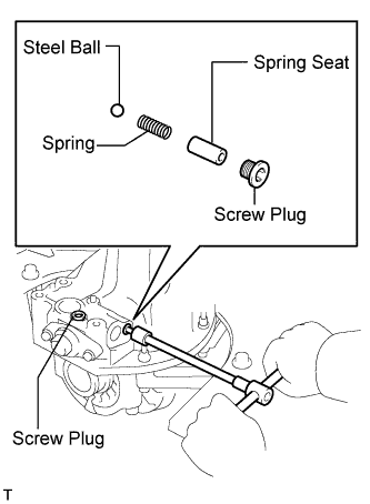 |
Using a 6 mm hexagon wrench, remove the 2 screw plugs.
Remove the spring seat, spring and steel ball.
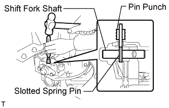 |
Using a 5 mm pin punch and hammer, tap out the slotted spring pin from the shift fork shaft.
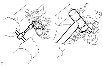 |
Remove the 2 bolts from the shaft retainer.
Using a plastic-faced hammer, tap on the retainer to separate it from the differential case.
Remove the shift fork shaft.
| 10. REMOVE REAR DRIVE PINION NUT |
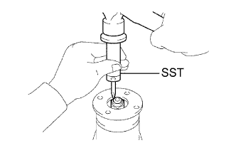 |
Using SST and a hammer, loosen the staked part of the nut.
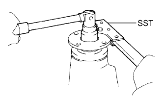 |
Using SST to hold the companion flange in place, remove the nut.
| 11. REMOVE REAR DRIVE PINION COMPANION FLANGE SUB-ASSEMBLY |
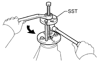 |
Using SST, remove the companion flange.
| 12. REMOVE REAR DIFFERENTIAL DUST DEFLECTOR |
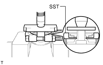 |
Using SST and a press, press out the dust deflector.
| 13. REMOVE REAR DIFFERENTIAL CARRIER OIL SEAL |
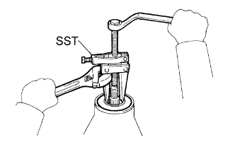 |
Using SST, remove the oil seal from the differential carrier.
| 14. REMOVE REAR DIFFERENTIAL DRIVE PINION OIL SLINGER |
| 15. REMOVE REAR DRIVE PINION FRONT TAPERED ROLLER BEARING |
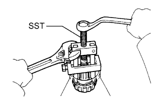 |
Using SST, remove the roller bearing (inner) from the drive pinion.
| 16. REMOVE REAR DIFFERENTIAL BEARING ADJUSTING NUT LOCK |
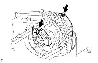 |
Remove the 2 bolts and 2 adjusting locks.
| 17. REMOVE DIFFERENTIAL CASE ASSEMBLY |
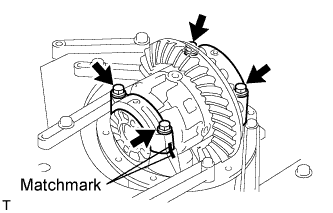 |
Place matchmarks on the bearing cap and differential carrier.
Remove the 4 bolts and 2 differential bearing caps.
Remove the 2 adjusting nuts.
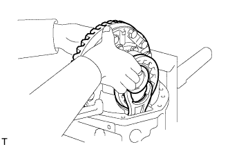 |
Remove the rear differential case assembly from the differential carrier.
| 18. REMOVE DIFFERENTIAL DRIVE PINION |
Remove the drive pinion and bearing spacer from the differential carrier.
| 19. REMOVE REAR DRIVE PINION REAR TAPERED ROLLER BEARING |
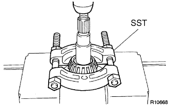 |
Using SST and a press, press out the roller bearing (inner) from the drive pinion.
| 20. REMOVE REAR DIFFERENTIAL DRIVE PINION PLATE WASHER |
| 21. REMOVE REAR DRIVE PINION FRONT TAPERED ROLLER BEARING |
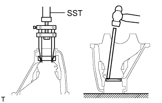 |
Using SST, remove the roller bearing (outer) from the carrier.
Using a brass bar and hammer, tap out the oil storage ring from the carrier.
| 22. REMOVE REAR DRIVE PINION REAR TAPERED ROLLER BEARING |
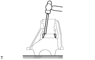 |
Using a brass bar and hammer, tap out the rear tapered roller bearing (outer) from the carrier.
| 23. REMOVE DIFFERENTIAL RING GEAR |
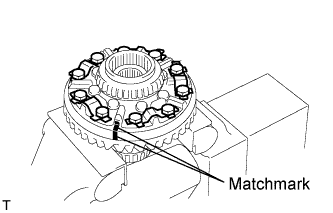 |
Place matchmarks on the ring gear and differential case.
Using a screwdriver and hammer, pry out the lock plates.
Remove the 10 ring gear set bolts and 5 lock plates.
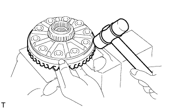 |
Using a plastic-faced hammer, tap on the ring gear to separate it from the differential case.
| 24. INSPECT DIFFERENTIAL CASE ASSEMBLY RUNOUT |
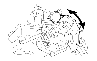 |
Install the rear differential case bearing to the differential case.
Install the differential case to the differential carrier.
Install the 2 bearing caps to the differential carrier with the 4 bolts.
Using dial indicator, measure the differential case runout.
Remove the differential case.
Remove the rear differential case bearing.
| 25. REMOVE REAR DIFFERENTIAL CASE BEARING |
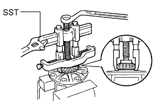 |
Using SST, remove the 2 bearings from the differential case.
| 26. DISASSEMBLE DIFFERENTIAL CASE |
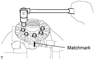 |
Place matchmarks on the LH and RH cases.
Remove the 8 bolts uniformly, a little at a time.
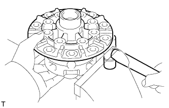 |
Using a plastic-faced hammer, tap out the LH case from RH case.
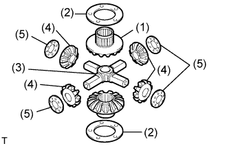 |
Remove the following parts from the differential cases.
| 27. INSPECT REAR DIFFERENTIAL LOCK SLEEVE |
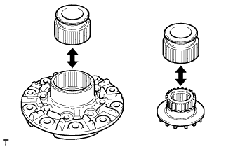 |
Install the sleeve to the differential case LH and check that it moves smoothly.
Install the sleeve to the side gear and check that it moves smoothly.
| 28. INSPECT SHIFT FORK AND SLEEVE |
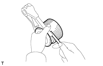 |
Using a feeler gauge, measure the clearance between the shift fork and sleeve.
| 29. INSPECT DIFFERENTIAL PINION AND SIDE GEAR |
Check that the differential pinion and differential side gear are not worn.
| 30. INSPECT DIFFERENTIAL CASE |
Check that the differential case is not damaged.