 |
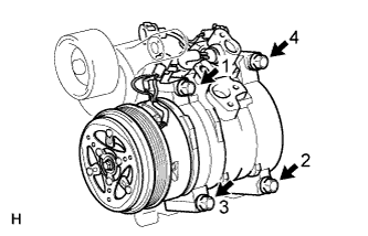
Install the compressor with the 4 bolts and tighten the bolts in the order shown in the illustration.
- Torque:
- 24.5 N*m{ 250 kgf*cm , 18 ft.*lbf }
COMPRESSOR AND MAGNETIC CLUTCH (for TR Series Engine) > INSTALLATION |
| 1. ADJUST COMPRESSOR OIL |
When replacing the compressor and magnet clutch with a new one, gradually discharge the refrigerant gas from the service valve, and drain the following amount of oil from the new compressor and magnet clutch before installation.
| 2. INSTALL COOLER COMPRESSOR ASSEMBLY |
|
Install the compressor with the 4 bolts and tighten the bolts in the order shown in the illustration.
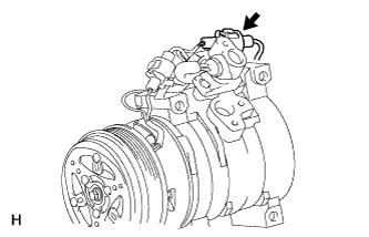 |
Connect the connector.
| 3. INSTALL NO. 1 COOLER REFRIGERANT DISCHARGE HOSE |
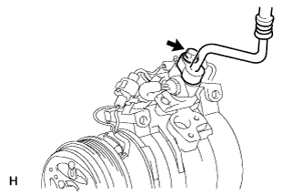 |
Remove the vinyl tape attached to the hose.
Sufficiently apply compressor oil to a new O-ring and the fitting surface of the compressor.
Install the O-ring to the discharge hose.
Connect the discharge hose with the bolt.
| 4. INSTALL SUCTION HOSE SUB-ASSEMBLY |
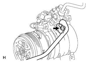 |
Remove the vinyl tape attached to the hose.
Sufficiently apply compressor oil to a new O-ring and the fitting surface of the compressor.
Install the O-ring to the suction hose.
Connect the suction hose with the bolt.
| 5. INSTALL DRIVE BELT |
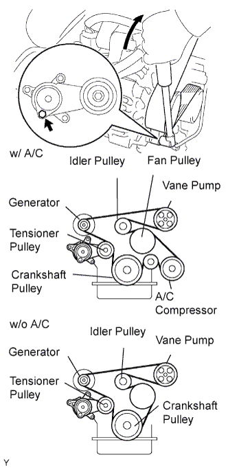 |
Install the drive belt to the pulleys except the drive belt tensioner pulley.
Use the hexagon-shaped part indicated by the arrow in the illustration to move the tensioner pulley downward and then install the drive belt to the tensioner pulley.
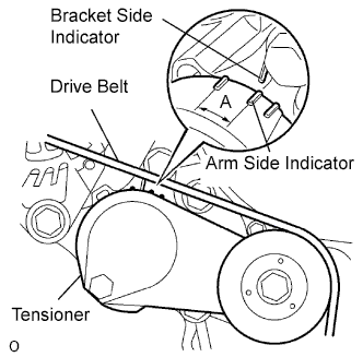 |
After a new belt has been installed, check that the tensioner indicator mark is within range A shown in the illustration.
| 6. CONNECT CABLE TO NEGATIVE BATTERY TERMINAL |
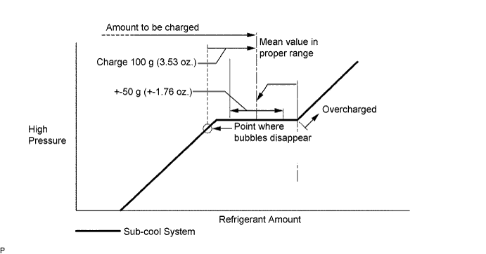
| 7. CHARGE REFRIGERANT |
Perform vacuum purging using a vacuum pump.
Charge refrigerant HFC-134a (R134a).
| 8. WARM UP ENGINE |
Warm up the engine at less than 1,850 rpm for 2 minutes or more after charging refrigerant.
| 9. CHECK FOR LEAKAGE OF REFRIGERANT |
After recharging the refrigerant gas, prepare the vehicle for a refrigerant gas leakage check by making sure the following conditions are met.
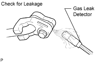 |
Check for refrigerant gas leakage from the refrigerant line.
After the blower motor stops, wait at least 15 minutes.
Using a gas leak detector, check that gas is not leaking from the refrigerant line. If leakage is found, tighten parts or replace damaged parts as necessary to stop the leak.
Check for refrigerant gas leakage from the cooling unit.
Hold the gas leak detector so that the sensor is under the drain hose, as shown in the illustration.
Check that gas is not leaking from the drain hose. If leakage is found, tighten parts or replace damaged parts as necessary to stop the leak.
Check for refrigerant gas leakage from the cooling unit.
Remove the blower motor control from the unit. Insert the gas leak detector's sensor into the unit.
Check that gas is not leaking from the unit. If leakage is found, tighten parts or replace damaged parts as necessary to stop the leak.
Check for refrigerant gas leakage from the pressure switch.
Disconnect the pressure switch connector and wait approximately 20 minutes.
Using a gas leak detector, check that gas is not leaking from the pressure switch. If leakage is found, tighten parts or replace damaged parts as necessary to stop the leak.
Repeat all steps above 2 to 3 times.