Warm up the engine.
Turn the ignition switch OFF.
Connect the intelligent tester to the DLC3.
Turn the ignition switch ON.
Turn the intelligent tester ON.
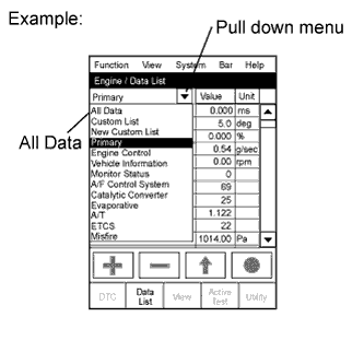 |
Enter the following menus: Powertrain / Engine / Data List.
- HINT:
- To display the entire Data List, press the pull down menu button next to Primary. Then select All Data.
Read the Data List.
| Tester Display | Measurement Item/Range | Normal Condition | Diagnostic Note |
| Calculate Load | Calculated load by ECM: Min.: 0%, Max.: 100% |
| - |
| MAF | Air flow rate from MAF meter status: Min.: 0 gm/sec., Max.: 655.35 gm/sec. |
| If value approximately 0 gm/sec.:
|
| MAP | Absolute pressure inside intake manifold: Min.: 0 kPa, Max.: 255 kPa |
| - |
| Engine Speed | Engine speed: Min.: 0 rpm, Max.: 16,383.75 rpm | 700 to 800 rpm: Idling | - |
| Vehicle Speed | Vehicle speed: Min.: 0 km/h, Max.: 255 km/h | Actual vehicle speed | Speed indicated on speedometer |
| Coolant Temp | Engine coolant temperature: Min.: -40°C, Max.: 140°C | 75 to 90°C (167 to 194°F): After warming up engine | If value is -40°C (-40°F) or 140°C (284°F), sensor circuit open or shorted |
| Intake Air | Intake air temperature: Min.: -40°C, Max.: 140°C | Equivalent to temperature at location of mass air flow meter | If value is -40°C (-40°F) or 140°C (284°F), sensor circuit open or shorted |
| Fuel Press | Fuel pressure: Min.: 0 kPa, Max.: 655350 kPa | 30,000 to 40,000 kPa: Idling | - |
| EGR Position | EGR position: Min: 0%, Max: 100% | Level surface, engine warmed up and idling: 0 to 65% | - |
| Accelerator Position No. 1 | Accelerator position No. 1: Min.: 0%, Max.: 100% |
| Read value with ignition switch ON (do not start engine) |
| Accelerator Position No. 2 | Accelerator position No. 2: Min.: 0%, Max.: 100% |
| Read value with ignition switch ON (do not start engine) |
| Throttle Motor | Throttle motor: ON or OFF | ON: Idling | - |
| Initial Engine Coolant Temp | Initial engine coolant temperature: Min.: -40°C, Max.: 120°C | ECT when engine starts | - |
| Initial Intake Air Temp | Initial intake air temperature: Min.: -40°C, Max.: 120°C | IAT when engine starts | - |
| Intake Air Temp (Turbo) | Intake air temperature: Min.: -40°C, Max.: 190°C | - | - |
| EGR Lift Position | EGR lift position: Min.: 0%, Max.: 100% | 0 to 65%: Idling | - |
| EGR Close Learning Value | EGR close learning value: Min.: 0 V, Max.: 5 V | 0.15 to 1.45 V | - |
| Throttle Valve Fully Closed | Throttle valve fully closed Min.: 0 deg, Max.: 84 deg | 11 to 21 deg | - |
| Target Common Rail Pressure | Target common rail pressure: Min.: 0 kPa, Max.: 655,350 kPa | 30,000 to 160,000 kPa | - |
| VNT Type | VN turbo type: Not or Commo or Vacuum | Commo | - |
| VNT Max Angle | VN turbo max angle: Min.: 0%, Max.: 100% | 90%: Idling | - |
| VNT Min Angle | VN turbo min angle: Min.: 0%, Max.: 100% | 10 to 20%: Full throttle | - |
| Injection Pressure Correction | Injection pressure correction: Min.: -500 mm3/st, Max.: 780 mm3/st | -400 to 400 mm3/st | - |
| EGR Valve Learning Value | EGR valve learning value: Min.: 0 V, Max.: 5 V | 0 to 1.0 V: Idling | - |
| Alternate Duty Ratio | Alternate duty ratio: Min.: 0%, Max.: 100% |
| - |
| Accel Position 1 | Accelerator pedal position sensor No. 1 voltage: Min.: 0 V, Max.: 5 V |
| Read value with ignition switch ON (do not start engine) |
| Accel Position 2 | Accelerator pedal position sensor No. 2 voltage: Min.: 0 V, Max.: 5 V |
| Read value with ignition switch ON (do not start engine) |
| Accel Position | Accelerator position status: Min.: 0%, Max.: 100% |
| Read value with ignition switch ON (do not start engine) |
| Fuel Temperature | Fuel temperature: Min.: -40°C, Max.: 140°C | Actual fuel temperature | ECD freeze frame data |
| Diesel Throttle Angle | Diesel throttle angle: Min.: -20%, Max.: 120% | Idling after engine warmed-up: 79 to 93% | ECD freeze frame data |
| VNT Command | VN turbo command: Min.: 0%, Max.: 100% | 0 to 100% | ECD freeze frame data |
| Pump VCM Angle | Pump VCM angle: Min.: 0 mA, Max.: 4,000 mA | 1,000 to 1,200 mA | ECD freeze frame data |
| IDL Stable Control | IDL stable control: Min.: -80 mm3/st, Max.: 79 mm3/st | -10 to 10 mm3/st | ECD freeze frame data |
| Common Rail Pres Sens 2 | Common rail pressure sensor (Sub) Min.: 0 kPa, Max.:655350 kPa | 30,000 to 40,000 kPa: Idling | - |
| Pilot 1 Injection | Pilot 1 injection: Min.: 0 μs, Max.: 65,535 μs | 380 to 480 μs: Idling | - |
| Pilot 2 Injection | Pilot 2 injection: Min.: 0 μs, Max.: 65,535 μs | 380 to 480 μs: Idling | - |
| Main Injection | Main injection: Min.: 0 μs, Max.: 65,535 μs | 510 to 710 μs: Idling | - |
| After Injection | After injection: Min.: 0 μs, Max.: 65,535 μs | - | - |
| Pilot 1 Injection | Pilot 1 injection: Min.: -70°CA, Max.: 20°CA | -22 to -18°CA: idle after engine warmed up and vehicle is under normal atmospheric pressure | - |
| Pilot 2 Injection | Pilot 2 injection: Min.: -50°CA, Max.: 20°CA | -16 to -11°CA: idle after engine warmed up and vehicle is under normal atmospheric pressure | - |
| Main Injection | Main injection: Min.: -90°CA, Max.: 90°CA | 0.5 to 4°CA: idle after engine warmed up and vehicle is under normal atmospheric pressure | - |
| After Injection | After injection: Min.: -10°CA, Max.: 50°CA | - | - |
| Injection Feedback Value | Injection volume feedback learning value: Min.: -10 mm3/st, Max.: 9.92 mm3/st | -4.0 to 4.0 mm3/st: Idling | - |
| Injection Feedback Val #1 | Injection volume correction for cylinder 1: Min.: -10 mm3/st, Max.: 10 mm3/st | -3.0 to 3.0 mm3/st: Idling | - |
| Injection Feedback Val #2 | Injection volume correction for cylinder 2: Min.: -10 mm3/st, Max.: 10 mm3/st | -3.0 to 3.0 mm3/st: Idling | - |
| Injection Feedback Val #3 | Injection volume correction for cylinder 3: Min.: -10 mm3/st, Max.: 10 mm3/st | -3.0 to 3.0 mm3/st: Idling | - |
| Injection Feedback Val #4 | Injection volume correction for cylinder 4: Min.: -10 mm3/st, Max.: 10 mm3/st | -3.0 to 3.0 mm3/st: Idling | - |
| Injection Volume | Injection volume: Min.: 0 mm3/st, Max.: 1,279.98 mm3/st | 5 to 12 mm3/st: Idling | - |
| Starter Signal | Starter signal: ON or OFF | ON: Cranking | - |
| A/C Signal | A/C signal: ON or OFF | ON: A/C ON | - |
| Stop Light Switch | Stop light switch: ON or OFF |
| - |
| Diesel Throttle Learn Status | Diesel throttle learn status: OK or NG | OK | - |
| EGR Learning Status | EGR learning status: OK or NG | OK | - |
| Swirl Control Valve VSV | VSV for No. 1 Swirl control valve status: ON or OFF | ON: Idling | - |
| ETCS Actuator Power | Whether or not electric throttle control system power input ON or OFF | ON: Idling | - |
| Battery Voltage | Battery voltage: Min.: 0 V, Max.: 65.535 V | 9 to 14 V: Idling | - |
| Actuator Power Supply | Actuator power supply ON or OFF | ON: Idling | - |
| Atmosphere Pressure | Atmospheric pressure value: Min.: 0 kPa, Max.: 255 kPa | Actual atmospheric pressure | - |
| EGR | EGR status for Active Test: ON or OFF | - | Active Test support date |
| ACT VSV | A/C cut status for Active Test: ON or OFF | - | Active Test support date |
| TC and TE1 | TC and TE1 terminal of DLC3: ON or OFF | - | Active Test support date |
| ACM Inhibit | ACM inhibit status: ON or OFF | - | Active Test support date |
| #Code | #Code: Min.: 0, Max.: 255 | - | Number of detected DTCs |
| Check Mode | Check mode: ON or OFF | ON: Check mode ON | - |
| SPD Test | Check mode result for vehicle speed sensor: Compl or Incompl | - | - |
| MIL ON Run Distance | MIL ON run distance: Min.: 0 km, Max.: 65,535 km | Distance after DTC detected | - |
| Running Time from MIL ON | Running time from MIL ON: Min.: 0 minute, Max.: 65,535 minutes | Equivalent running time after MIL was ON | - |
| Engine Run Time | Engine run time: Min.: 0 seconds, Max.: 65,535 seconds | Time after engine started | Service data |
| Time After DTC Cleared | Time after DTC cleared: Min.: 0 minutes, Max.: 65,535 minutes | Equivalent to time after DTCs were erased | - |
| Distance from DTC Cleared | Distance after DTC cleared: Min.: 0 km, Max.: 65,535 km | Equivalent to drive distance after DTCs were erased | - |
| Warmup Cycle Cleared DTC | Warmup cycle after DTC cleared: Min.: 0, Max.: 255 | - | Number of warmup cycles after DTC cleared |
| Complete Parts Monitor | Complete parts monitor: Not Avl or Avail | - | - |
| Fuel System Monitor | Fuel system monitor: Not Avl or Avail | - | - |
| Model Code | Model code | - | Identifying model code: |
| Engine Type | Engine type | - | Identifying engine type: 1KDFTV |
| Cylinder Number | Cylinder number: Min.: 0, Max.: 255 | - | Identifying cylinder number: 4 |
| Transmission Type | Transmission type | - | Identifying transmission type: ECT 5th |
| Destination | Destination | - | Identifying destination: W |
| Model Year | Model year: Min.: 1900, Max.: 2155 | - | Identifying mode year: 200# |
| System Identification | System identification | - | Identifying engine type: Diesel |
- HINT:
- Normal Condition: If no idling conditions are specified, the shift lever is in the N position, and the A/C switch and all accessory switches are OFF.