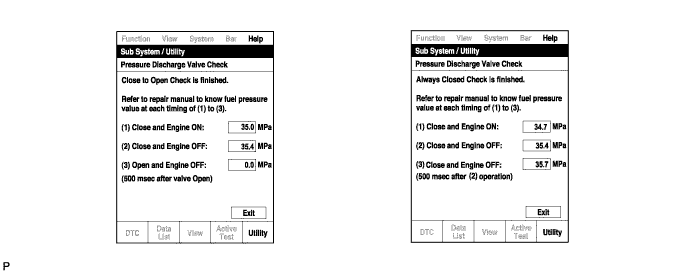
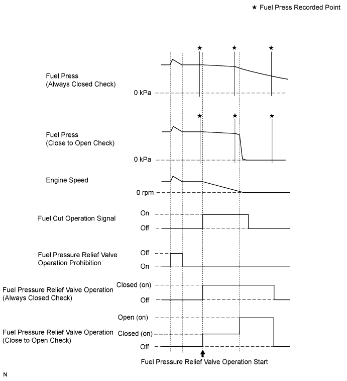
Warm up the engine.
Turn the ignition switch OFF.
Connect the intelligent tester to the DLC3.
Turn the ignition switch ON.
Turn the intelligent tester ON.
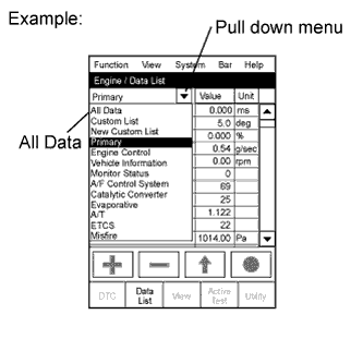 |
Enter the following menus: Powertrain / Engine and ECT / Data List.
- HINT:
- To display the entire Data List, press the pull down menu button next to Primary. Then select All Data.
Read the Data List.
| Tester Display | Measurement Item/Range | Normal Condition | Diagnostic Note |
| Vehicle Speed | Vehicle speed: Min.: 0 km/h, Max.: 255 km/h | Actual vehicle speed | Speed indicated on speedometer |
| Engine Speed | Engine speed: Min.: 0 rpm, Max.: 16,383.75 rpm | 700 to 800 rpm: Idling after engine warmed up | - |
| Calculate Load | Calculated load by ECM: Min.: 0%, Max.: 100% |
| - |
| MAF | Air flow rate from MAF meter: Min.: 0 g/sec., Max.: 655.35 g/sec. |
| If value approximately 0 g/sec.:
|
| Atmosphere Pressure | Atmospheric pressure value: Min.: 0 kPa, Max.: 255 kPa | Actual atmospheric pressure | - |
| MAP | Absolute pressure inside intake manifold: Min.: 0 kPa, Max.: 255 kPa |
| - |
| Coolant Temp | Engine coolant temperature: Min.: -40°C, Max.: 140°C | 80 to 95°C (176 to 203°F): After engine warmed up | If value is -40°C (-40°F) or 140°C (284°F), sensor circuit open or shorted |
| Intake Air | Intake air temperature: Min.: -40°C, Max.: 140°C | Equivalent to temperature at location of mass air flow meter | If value is -40°C (-40°F) or 140°C (284°F), sensor circuit open or shorted |
| Intake Air Temp (Turbo) | Intake air temperature after intercooler: Min.: -40°C, Max.: 140°C | Changes depending on operating conditions | - |
| Engine Run Time | Engine run time: Min.: 0 seconds, Max.: 65,535 seconds | Time after engine started | Service data |
| Initial Engine Coolant Temp | Initial engine coolant temperature: Min.: -40°C, Max.: 120°C | ECT when engine starts | - |
| Initial Intake Air Temp | Initial intake air temperature: Min.: -40°C, Max.: 120°C | Intake air temperature when engine starts | - |
| Battery Voltage | Battery voltage: Min.: 0 V, Max.: 65.535 V | 9 to 14 V: Idling | - |
| Alternate Duty Ratio | Alternate duty ratio: Min.: 0%, Max.: 100% |
| - |
| Pre Glow | Pre-glow operation: ON or OFF | - | This is the ECM command. |
| After Glow | After-glow operation: ON or OFF | - | This is the ECM command. |
| Accel Position | Accelerator position status: Min.: 0%, Max.: 100% |
| Read value with ignition switch ON (do not start engine) |
| Accel Sens. No.1 Volt % | Accelerator position No. 1: Min.: 0%, Max.: 100% |
| Read value with ignition switch ON (do not start engine) |
| Accel Sens. No.2 Volt % | Accelerator position No. 2: Min.: 0%, Max.: 100% |
| Read value with ignition switch ON (do not start engine) |
| Target Throttle Position | Target throttle position: Min.: -128%, Max.: 127% |
| If there is a malfunction of the throttle actuator, compare the target and actual throttle position values for troubleshooting. |
| Actual Throttle Position | Actual diesel throttle position: Min.: -20%, Max.: 120% | - | - |
| Throttle Close Learning Val. | Throttle fully closed position learned value: Min.: 0 deg, Max.: 84 deg | - | - |
| Diesel Throttle Learn Status | Diesel throttle learning status: OK or NG | OK | - |
| Injection Volume | Injection volume: Min.: 0 mm3/st, Max.: 1,279.98 mm3/st | 3 to 10 mm3/st: Idling | - |
| Inj. FB Vol. for Idle | Idle stability status integral control volume: Min.: -80 mm3/st, Max.: 79.9975 mm3/st | -10 to 10 mm3/st | - |
| Inj Vol Feedback Learning | Injection volume compensation learned value: Min.: -10 mm3/st, Max.: 9.92 mm3/st | -4.0 to 4.0 mm3/st: Idling | - |
| Injection Feedback Val #1 | Injection volume correction for cylinder 1: Min.: -10 mm3/st, Max.: 10 mm3/st | -3.0 to 3.0 mm3/st: Idling |
|
| Injection Feedback Val #2 | Injection volume correction for cylinder 2: Min.: -10 mm3/st, Max.: 10 mm3/st | -3.0 to 3.0 mm3/st: Idling | |
| Injection Feedback Val #3 | Injection volume correction for cylinder 3: Min.: -10 mm3/st, Max.: 10 mm3/st | -3.0 to 3.0 mm3/st: Idling | |
| Injection Feedback Val #4 | Injection volume correction for cylinder 4: Min.: -10 mm3/st, Max.: 10 mm3/st | -3.0 to 3.0 mm3/st: Idling | |
| Pilot 1 Injection Period | Pilot 1 injection period: Min.: 0 μs, Max.: 65,535 μs | 350 to 450 μs: Idling | - |
| Pilot 2 Injection Period | Pilot 2 injection period: Min.: 0 μs, Max.: 65,535 μs | 350 to 450 μs: Idling | - |
| Main Injection Period | Main injection period: Min.: 0 μs, Max.: 65,535 μs | 450 to 640 μs: Idling | - |
| After Injection Period | After injection period: Min.: 0 μs, Max.: 65,535 μs | - | - |
| Pilot 1 Injection Timing | Pilot 1 injection timing: Min.: -70°CA, Max.: 20°CA | -14.2 to -13.2°CA: Idling after engine warmed up and vehicle is under normal atmospheric pressure | - |
| Pilot 2 Injection Timing | Pilot 2 injection timing: Min.: -50°CA, Max.: 20°CA | -7.7 to -6.7°CA: Idling after engine warmed up and vehicle is under normal atmospheric pressure | - |
| Main Injection Timing | Main injection timing: Min.: -90°CA, Max.: 90°CA | 2.8°CA: Idling after engine warmed up and vehicle is under normal atmospheric pressure | - |
| After Injection Timing | After injection timing: Min.: -10°CA, Max.: 50°CA | - | - |
| Injector Memory Error | Injector Memory Error: No Error or Error | No Error | If the fuel injector compensation codes are not input into the new ECM, or if a fuel injector compensation code of a different injector model or a compensation code representing a value which exceeds the compensation setting range is input into the new ECM, DTC P1601 is stored and "Injector Memory Error" displays "Error". |
| Reju Pilot Quantity Learning | Pilot quantity learning prohibition state: READY or NG | - | - |
| Pilot Quantity Learning | State of "Pilot Quantity Learning": Standby / Wait / Learn / Stop / Comple | - | If "Pilot Quantity Learning" is incomplete, the MIL illuminates and DTC P1601 is stored. |
| Injection Pressure Correction | Injection pressure correction: Min.: -500 mm3/st, Max.: 780 mm3/st | -400 to 400 mm3/st | - |
| Target Common Rail Pressure | Target common rail pressure: Min.: 0 kPa, Max.: 655350 kPa | 20000 to 180000 kPa | - |
| Fuel Press | Fuel pressure: Min.: 0 kPa, Max.: 655350 kPa | 25000 to 35000 kPa: Idling | - |
| Common Rail Pres Sens 2 | Common rail pressure sensor (Sub) Min.: 0 kPa, Max.: 655350 kPa | 25000 to 35000 kPa: Idling | - |
| Fuel Temperature | Fuel temperature: Min.: -40°C, Max.: 215°C | Actual fuel temperature | ECD freeze frame data |
| Fuel Return Temp | Fuel return temperature: Min.: -40°C, Max.: 215°C | Idling after engine warmed up: 35 to 85°C | If the "Fuel Return Temp" value is not between 35°C (95°F) and 110°C (230°F), "Pilot Quantity Learning" is prohibited. |
| Target Pump SCV Current | Pump current target final value: Min.: 0 mA, Max.: 4000 mA | - | - |
| Fuel Pressure Relief Valve | Pressure discharge valve operation: ON or OFF | ON: Pressure discharge valve open | This is the ECM command. |
| Target EGR Position | EGR valve target opening angle: Min.: 0%, Max.: 100% | Level surface, engine warmed up and engine idling: 50 to 100% | - |
| Actual EGR Valve Pos. | EGR valve position: Min.: 0%, Max.: 100% | Idling after engine warmed up: 60 to 80% | - |
| EGR Lift Sensor Volt % | EGR lift position: Min.: 0%, Max.: 99.6% | - | - |
| EGR Close Learn Val. | EGR valve lift volume learned value: Min.: 0 V, Max.: 5 V | - | - |
| EGR Close Lrn. Val. | EGR fully closed position learned value: Min.: 0 V, Max.: 5 V | Level surface, room temperature, engine warmed up and engine idling: 0.15 to 1.45 V | - |
| EGR Close Lrn. Status | EGR valve fully closed position learning status: OK or NG | OK | - |
| EGR Operation Prohibit | EGR operation prohibition: OK or NG | OK: Active Test item "Control the EGR Step Position" can be performed |
|
| Target Booster Pressure | Target booster pressure: Min.: 0 kPa, Max.: 320 kPa | Idling and vehicle under normal atmospheric pressure: 95 to 105 kPa | - |
| VN Turbo Command | VN turbo command: Min.: 0%, Max.: 100% | 0 to 100% | "VN Turbo Command" is a command value. |
| VN Turbo Type | VN turbo type: Not or Commo or Vacuum | Commo | - |
| VN Turbo Max Angle | VN turbo max angle: Min.: 0%, Max.: 100% | 90%: Idling after engine warmedup | - |
| VN Turbo Min Angle | VN turbo min angle: Min.: 0%, Max.: 100% | 20 to 30%: Full throttle | - |
| Starter Signal | Starter signal: ON or OFF | ON: Cranking | - |
| Clutch Switch | Clutch switch: ON or OFF | ON: Clutch pedal depressed | - |
| Stop Light Switch | Stop light switch: ON or OFF |
| - |
| A/C Signal | A/C signal: ON or OFF | ON: A/C ON | - |
| Immobiliser Communication | Immobiliser communication: ON or OFF |
| - |
| Check Mode | Check mode: ON or OFF | ON: Check mode ON | - |
| SPD Test Result | Check mode result for vehicle speed sensor: Compl or Incompl | - | - |
| # Codes(Include History) | Number of codes: Min.: 0, Max.: 255 | - | Number of detected DTCs |
| MIL | MIL status: ON or OFF | ON: MIL ON | - |
| MIL ON Run Distance | MIL ON run distance: Min.: 0 km, Max.: 65535 km | Distance after DTC detected | - |
| Running Time from MIL ON | Running time from MIL ON: Min.: 0 minutes, Max.: 65535 minutes | Equivalent to running time after MIL turned ON | - |
| Time After DTC Cleared | Time after DTC cleared: Min.: 0 minutes, Max.: 65,535 minutes | Equivalent to time after DTCs were erased | - |
| Distance from DTC Cleared | Distance after DTC cleared: Min.: 0 km, Max.: 65,535 km | Equivalent to driving distance after DTCs were erased | - |
| Warmup Cycle Cleared DTC | Warmup cycles after DTC cleared: Min.: 0, Max.: 255 | - | Number of warmup cycles after DTC cleared |
| OBD Requirements | Identifying OBD requirement | - | - |
| Number of Emission DTC | Number of emissions-related DTCs | - | - |
| TC and TE1 | TC and TE1 terminal of DLC3: ON or OFF | - | Active Test support data |
| Engine Start Time | Engine start time: Min.: 0 ms, Max.: 267000 ms | - | Time necessary for the engine to start. |
| Engine Speed (Starter Off) | Engine speed when starter off: Min.: 0 rpm, Max.: 1593 rpm | - | Engine speed immediately after starting the engine. |
| Starter Count | Starter on count: Min.: 0, Max.: 255 | - | Number of times the starter turned on from the time the ignition switch was turned to ON. |
| Run Dist of Previous Trip | Distance driven during previous trip: Min.: 0 km, Max.: 326 km | - | Used to confirm the driving conditions of the previous trip (before the malfunction occurred). |
| Electric Duty Feedback Value | Electric load feedback value: Min.: 0 mm3/st, Max.: 39.8 mm3/st | 0 to 10 mm3/st | Expected injection volume increase after the electrical load turns from off to on. |
| A/C Duty Feedback Value | A/C load feedback value: Min.: 0 mm3/st, Max.: 39.8 mm3/st | 0 to 10 mm3/st | Expected injection volume increase after the A/C turns from off to on. |
| PS Duty Feedback Value | Power steering load feedback value: Min.: 0 mm3/st, Max.: 39.8 mm3/st | 0 to 10 mm3/st | Expected injection volume increase after the power steering turns from off to on. |
| Idle Injection Volume (Min) | Injection volume feedback learned value: Min.: 0 mm3/st, Max.: 39.8 mm3/st | 0 to 5 mm3/st |
|
| Swirl Control Valve VSV | VSV for swirl control valve status: ON or OFF | ON: Idling | - |
| ACT VSV | A/C cut status for Active Test: ON or OFF | - | Active Test support data |
| Model Code | Model code | - | Identifying model code |
| Engine Type | Engine type | - | Identifying engine type: 2KDFTV |
| Cylinder Number | Cylinder number: Min.: 0, Max.: 255 | - | Identifying cylinder number: 4 |
| Transmission Type | Transmission type | - | Identifying transmission type: MT / ECT 4th / ECT 5th |
| Destination | Destination | - | Identifying destination: W / Q |
| Model Year | Model year: Min.: 1900, Max.: 2155 | - | Identifying model year: 200# |
| System Identification | System Identification | - | - |
| Engine Speed of Cyl #1 | Engine speed for No. 1 cylinder: Min.: 0 rpm, Max.: 51199 rpm | "Engine speed" of all cylinders almost same |
|
| Engine Speed of Cyl #2 | Engine speed for No. 2 cylinder: Min.: 0 rpm, Max.: 51199 rpm | "Engine speed" of all cylinders almost same | As above |
| Engine Speed of Cyl #3 | Engine speed for No. 3 cylinder: Min.: 0 rpm, Max.: 51199 rpm | "Engine speed" of all cylinders almost same | As above |
| Engine Speed of Cyl #4 | Engine speed for No. 4 cylinder: Min.: 0 rpm, Max.: 51199 rpm | "Engine speed" of all cylinders almost same | As above |
| Av Engine Speed of All Cyl | Engine speed for all cylinders: Min.: 0 rpm, Max.: 51199 rpm | - | As above |
- HINT:
- Normal Condition: If no idling conditions are specified, the shift lever should be in the neutral position, and the A/C switch and all accessory switches should be OFF.