| NG |  |
| REPAIR FUEL LEAK POINT |
DTC P0093/78 Fuel System Leak Detected - Large Leak |
| DTC No. | DTC Detection Condition | Trouble Area |
| P0093/78 | Fuel leaks in high-pressure areas (1 trip detection logic) |
|
| Engine Speed | Fuel Pressure |
| Idling | Approximately 25000 to 35000 kPa |
| 3,000 rpm (No engine load) | Approximately 35000 to 55000 kPa |
| Required sensors | Fuel pressure sensor |
| Frequency of operation | Continuous |
| Duration | 1 second |
| MIL operation | 1 driving cycle |
| Item | Specification Minimum | Specification Maximum |
| Engine speed | 600 rpm | - |
| The monitor will not run if the fuel pressure sensor or suction control valve circuit is malfunctioning | ||
| Threshold |
| Drop of the internal fuel pressure is large when injecting fuel |
| 1.CHECK FOR FUEL LEAKS (IN HIGH-PRESSURE AREAS) |
Before starting the engine, visually check for fuel leaks from the fuel supply pump, fuel injectors, common rail, and the fuel pipes in high-pressure areas.
|
| ||||
| OK | |
 |
| 2.CHECK FOR ANY OTHER DTC OUTPUT (IN ADDITION TO DTC P0093/78) |
Connect the intelligent tester to the DLC3.
Turn the ignition switch ON and turn the intelligent tester ON.
Enter the following menus: Powertrain / Pick Up / Engine / DTC.
Read the DTCs.
| Display (DTC Output) | Proceed to |
| P0093/78 | A |
| P0093/78 and other Current DTCs | B |
|
| ||||
| A | |
|
| 3.CHECK FREEZE FRAME DATA |
Connect the intelligent tester to the DLC3.
Turn the ignition switch ON and turn the intelligent tester ON.
Enter the following menus: Powertrain / Pick Up / Engine / DTC.
Record the stored DTC and Freeze Frame Data.
| Tester Display (Freeze Frame Data Item) | Measurement Item | Standard (Reference) |
| Target Pump SCV Current | Target current value flowing to the SCV of the fuel supply pump | 800 to 3000 mA |
| Fuel Press | Actual fuel pressure inside the common rail |
|
| Injection Feedback Val #1 Injection Feedback Val #2 Injection Feedback Val #3 Injection Feedback Val #4 | Injection volume correction value for each cylinder | Between -4.9 mm3/st and 4.9 mm3/st |
| NEXT | |
|
| 4.CHECK FREEZE FRAME DATA (TARGET PUMP SCV CURRENT) |
Turn the tester ON.
Read the value of Target Pump SCV Current recorded in the Freeze Frame Data.
| Tester Display | Specified Condition |
| Target Pump SCV Current | 800 to 3000 mA |
|
| ||||
| OK | |
|
| 5.CHECK FUEL RECEIVER GAUGE (AMOUNT OF FUEL) |
Check if the fuel level is low.
| Result | Proceed to |
| The indicator (fuel warning light) is illuminated | A |
| The indicator (fuel warning light) is not illuminated | B |
|
| ||||
| A | |
|
| 6.ADD FUEL |
| NEXT | |
|
| 7.CHECK WHETHER DTC OUTPUT RECURS (DTC P0093/78) |
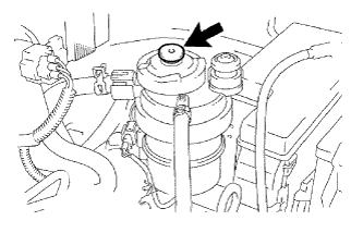 |
Using the hand pump mounted on the fuel filter cap, bleed the air from the fuel system. Continue pumping until the pump resistance increases.
Start the engine.
When the engine can be started, proceed to the next step.
If the engine cannot be started, bleed the air again using the hand pump until the hand pump resistance increases. Then start the engine.
Turn the ignition switch off.
Connect the intelligent tester to the DLC3.
Turn the ignition switch ON and turn the intelligent tester ON.
Clear DTCs.
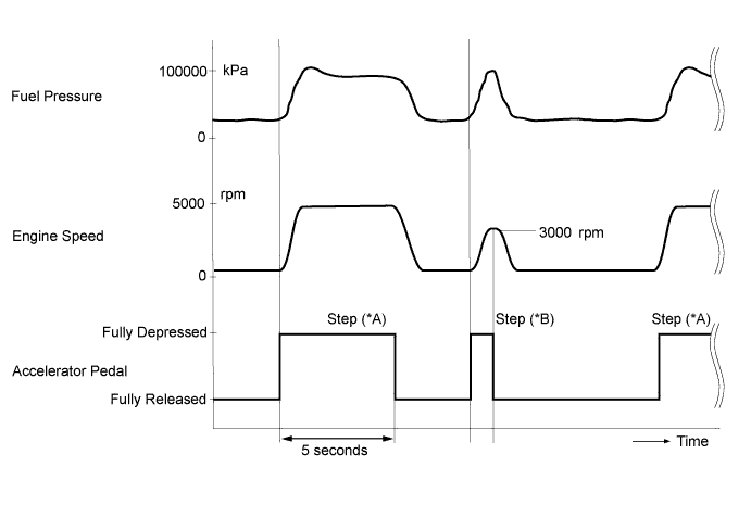
Start the engine. (*A)
Enter the following menus: Powertrain / Pick Up / Engine / Active Test / Test the Fuel Leak. (*B)
Perform the following test 5 times with on/off intervals of 10 seconds: Active Test / Test the Fuel Leak. (*C)
Allow the engine to idle for 3 minutes or more after performing the Active Test for the fifth time. (*D)
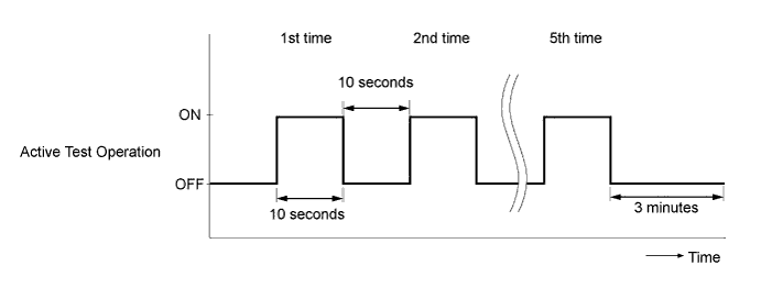
Enter the following menus: Powertrain / Pick Up / Engine / DTC.
Read Current DTCs.
When no DTCs are output, the air bleeding is completed.
If any DTCs are output, proceed to the next step.
Repeat steps (*A) to (*D).
Clear DTCs.
Start the engine and warm it up.
Confirm that the shift lever is in neutral, and securely apply the parking brake.
Fully depress the accelerator pedal for 5 seconds and then release it. (*E)
Rev the engine to 3000 rpm and fully release the accelerator pedal immediately after the engine reaches 3000 rpm. (*F)
Repeat the above procedures (*E) and (*F) 5 times.
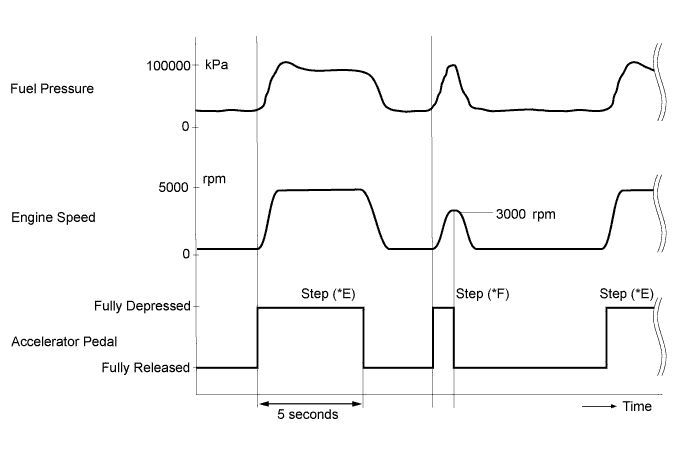
Enter the following menus: Powertrain / Pick Up / Engine / DTC.
Read Current DTCs.
| Display (DTC Output) | Proceed to |
| DTC output | A |
| DTC not output | B |
|
| ||||
| A | |
|
| 8.CHECK FREEZE FRAME DATA (INJECTION FEEDBACK VAL #1 TO #4) |
Turn the tester ON.
Read the value of Injection Feedback Val #1 to #4 recorded in the Freeze Frame Data.
| Result | Proceed to |
| -4.9 to 4.9 mm3/st | A |
| -5 mm3/st or 5 mm3/st | B |
|
| ||||
| A | |
|
| 9.CHECK ENGINE STARTING CONDITION |
Check whether the engine can be started within 4 seconds.
|
| ||||
| OK | |
|
| 10.PERFORM ACTIVE TEST USING INTELLIGENT TESTER (TEST THE FUEL LEAK) |
Connect the intelligent tester to the DLC3.
Turn the ignition switch to ON and turn the tester ON.
Enter the following menus: Powertrain / Pick Up / Engine / Active Test / Test the Fuel Leak / Data List / Fuel Press, Target Common Rail Pressure, and Target Pump SCV Current.
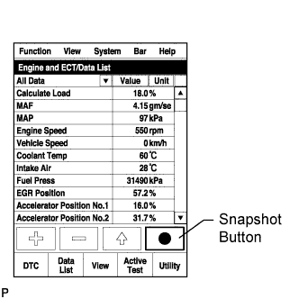 |
Take a snapshot with the intelligent tester during the Active Test.
Measure the difference between the target fuel pressure (Target Common Rail Pressure) and the actual fuel pressure (Fuel Press) when the Active Test / Test the Fuel Leak is performed (Click here).
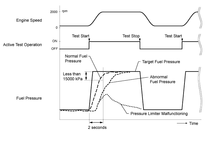
Read the value of Target Pump SCV Current in the Data List when the Active Test / Test the Fuel Leak is performed.
| Result | Proceed to |
| Difference between target fuel pressure and actual fuel pressure is 15000 kPa or more | B |
| Target Pump SCV Current value is out of standard range | C |
| Both results are within standard range | A |
|
| ||||
|
| ||||
| A | |
|
| 11.INSPECT FUEL TEMPERATURE SENSOR (SENSOR OUTPUT) |
Connect the intelligent tester to the DLC3.
Turn the ignition switch to ON and turn the tester ON.
Enter the following menus: Powertrain / Pick Up / Engine / Data List / Fuel Temperature.
Read the value.
|
| ||||
| OK | |
|
| 12.READ VALUE USING INTELLIGENT TESTER (ENGINE SPEED) |
Connect the intelligent tester to the DLC3.
Turn the ignition switch to ON and turn the tester ON.
Enter the following menus: Powertrain / Pick Up / Engine / Data List / Engine Speed.
Read the value while cranking and idling the engine.
| Tester Display | Engine Condition | Specified Condition |
| Engine Speed | Cranking | 50 to 400 rpm |
| Idling with warm engine | 700 to 800 rpm |
|
| ||||
| OK | |
|
| 13.INSPECT CAMSHAFT POSITION SENSOR (SENSOR RESISTANCE) |
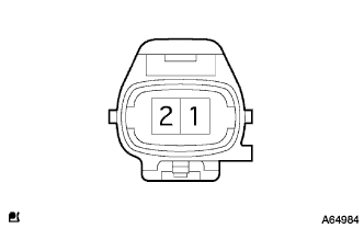 |
Disconnect the camshaft position sensor connector.
Measure the sensor resistance.
| Tester Connection | Condition | Specified Condition |
| 1 - 2 | Approx. 20°C (68°F) | 950 to 1250 Ω |
Reconnect the sensor connector.
|
| ||||
| OK | |
|
| 14.INSPECT HARNESS AND CONNECTOR (CAMSHAFT POSITION SENSOR - ECM) |
Disconnect the camshaft position sensor connector.
Disconnect the ECM connector.
Check for an open or short circuit in the wire harness and connectors between the ECM and camshaft position sensor.
Reconnect the ECM and sensor connectors.
|
| ||||
| OK | |
|
| 15.INSPECT ECM (FUEL PRESSURE SENSOR OUTPUT VOLTAGE) |
Connect the positive (+) probe of an oscilloscope to the fuel pressure sensor input terminal of the ECM connector and the negative (-) probe to the body ground.
Turn the ignition switch to ON.
Check for any noise in the waveform when vibration is applied to the wire harness and connectors between the fuel pressure sensor and ECM.
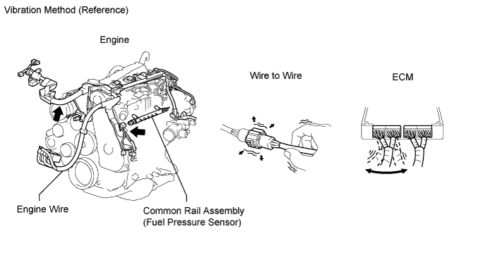
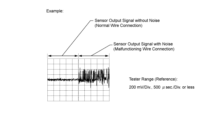
| Result | Proceed to |
| MIL comes on or noise exists in the waveform | B |
| Except above | A |
|
| ||||
| A | |
|
| 16.CHECK ENGINE OIL CONDITION |
Remove the oil filler cap (and the engine oil level dipstick), and check whether the engine oil smells of diesel fuel.
|
| ||||
| OK | |
|
| 17.CHECK FOR INTERMITTENT PROBLEMS |
Check for intermittent problems (Click here).
|
| ||||
| 18.PERFORM ACTIVE TEST USING INTELLIGENT TESTER (FUEL CUT FOR IDENTIFYING MALFUNCTION) |
Connect the intelligent tester to the DLC3.
Start the engine and turn the intelligent tester ON.
Enter the following menus: Powertrain / Pick Up / Engine / Active Test / Control the Cylinder #1, #2, #3 and #4 Fuel Cut.
Check the four cylinders in sequence to identify any faulty cylinders by performing the power balance inspection.
| Result | Proceed to |
| Malfunctioning cylinder not confirmed | A |
| Malfunctioning cylinder confirmed | B |
|
| ||||
| A | |
|
| 19.CHANGE ENGINE OIL |
Remove the oil pan drain plug and drain the engine oil.
Install the oil pan drain plug.
Remove the oil filler cap.
Add fresh oil and install the oil filler cap.
| NEXT | |
|
| 20.CHECK FOR INTERMITTENT PROBLEMS |
Check for intermittent problems (Click here).
|
| ||||
| 21.REPLACE FUEL INJECTOR (FUEL INJECTOR OF MALFUNCTIONING CYLINDER) |
Replace the fuel injectors of the malfunctioning cylinders.
| NEXT | |
|
| 22.REGISTER INJECTOR COMPENSATION CODE |
Register the injector compensation code (Click here).
| NEXT | |
|
| 23.BLEED AIR FROM FUEL SYSTEM |
Using the hand pump mounted on the fuel filter cap, bleed the air from the fuel system. Continue pumping until the pump resistance increases.
Start the engine.
When the engine can be started, proceed to the next step.
If the engine cannot be started, bleed the air again using the hand pump until the hand pump resistance increases. Then start the engine.
Turn the ignition switch off.
Connect the intelligent tester to the DLC3.
Turn the ignition switch to ON and turn the tester ON.
Clear DTCs.
Start the engine. (*A)
Enter the following menus: Powertrain / Pick Up / Engine / Active Test / Test the Fuel Leak. (*B)
Perform the following test 5 times with on/off intervals of 10 seconds: Active Test / Test the Fuel Leak. (*C)
Allow the engine to idle for 3 minutes or more after performing the Active Test for the fifth time. (*D)
Enter the following menus: Powertrain / Pick Up / Engine / DTC.
Read Current DTCs.
When no DTCs are output, the air bleeding is completed.
If any DTCs are output, proceed to the next step.
Clear DTCs.
Repeat steps (*A) to (*D).
| NEXT | |
|
| 24.CHANGE ENGINE OIL |
Remove the oil pan drain plug and drain the engine oil.
Install the oil pan drain plug.
Remove the oil filler cap.
Add fresh oil and install the oil filler cap.
|
| ||||
| 25.CLEAR DTC |
Connect the intelligent tester to the DLC3.
Turn the ignition switch to ON and turn the tester ON.
Enter the following menus: Powertrain / Pick Up / Engine / DTC.
Clear DTCs.
| NEXT | |
|
| 26.CHECK ENGINE START CONDITION |
Check whether the engine can be started within 4 seconds.
|
| ||||
|
| ||||
| 27.BLEED AIR FROM FUEL SYSTEM |
Using the hand pump mounted on the fuel filter cap, bleed the air from the fuel system. Continue pumping until the pump resistance increases.
Start the engine.
When the engine can be started, proceed to the next step.
If the engine cannot be started, bleed the air again using the hand pump until the hand pump resistance increases. Then start the engine.
Turn the ignition switch off.
Connect the intelligent tester to the DLC3.
Turn the ignition switch to ON and turn the tester ON.
Clear DTCs.
Start the engine. (*A)
Enter the following menus: Powertrain / Pick Up / Engine / Active Test / Test the Fuel Leak. (*B)
Perform the following test 5 times with on/off intervals of 10 seconds: Active Test / Test the Fuel Leak. (*C)
Allow the engine to idle for 3 minutes or more after performing the Active Test for the fifth time. (*D)
Enter the following menus: Powertrain / Pick Up / Engine / DTC.
Read Current DTCs.
When no DTCs are output, the air bleeding is completed.
If any DTCs are output, proceed to the next step.
Clear DTCs.
Repeat steps (*A) to (*D).
| NEXT | |
|
| 28.CHECK ENGINE START CONDITION |
Check whether the engine can be started.
|
| ||||
|
| ||||
| 29.CHECK AND REPLACE FUEL INLET LINE |
Check the following items, and repair or replace the malfunctioning part if necessary.
Check for fuel filter clogging.
Check for fuel freezing in the fuel line.
Check for clogging or leaks in the fuel pipe and hose between the fuel tank and fuel supply pump.
| NEXT | |
|
| 30.CHECK ENGINE START CONDITION |
Check whether the engine can be started.
|
| ||||
| OK | |
|
| 31.READ VALUE USING INTELLIGENT TESTER (INJECTION VALUE FEEDBACK VAL #1 TO #4) |
Start the engine and warm it up until the engine coolant temperature reaches 70°C (158°F) or higher.
Allow the engine to idle for 1 minute or more.
Connect the intelligent tester to the DLC3.
Turn the tester ON.
Enter the following menus: Powertrain / Pick Up / Engine / Data List / Target Pump SCV Current and Injector Feedback Val. #1 to #4 (Click here).
|
Take a snapshot with the intelligent tester.
Read the values.
| Tester Display | Engine Condition | Specified Condition |
| Injection Feedback Val #1 Injection Feedback Val #2 Injection Feedback Val #3 Injection Feedback Val #4 | Idling | Between -4.9 mm3/st and 4.9 mm3/st |
| Target Pump SCV Current | Idling and revving engine to 3000 rpm 5 times | 800 to 3000 mA |
| Result | Proceed to |
| Target Pump SCV Current value is out of standard range | B |
| Except above | A |
|
| ||||
| A | |
|
| 32.PERFORM ACTIVE TEST USING INTELLIGENT TESTER (FUEL CUT FOR IDENTIFYING MALFUNCTION) |
Connect the intelligent tester to the DLC3.
Start the engine and turn the intelligent tester ON.
Enter the following menus: Powertrain / Pick Up / Engine / Active Test / Control the Cylinder #1, #2, #3 and #4 Fuel Cut.
Check the four cylinders in sequence to identify any faulty cylinders by performing the power balance inspection.
| NEXT | |
|
| 33.REPLACE FUEL INJECTOR (FUEL INJECTOR OF MALFUNCTIONING CYLINDER) |
Replace the fuel injectors of the malfunctioning cylinders.
| NEXT | |
|
| 34.REGISTER INJECTOR COMPENSATION CODE |
Register the injection compensation code (Click here).
| NEXT | |
|
| 35.BLEED AIR FROM FUEL SYSTEM |
Using the hand pump mounted on the fuel filter cap, bleed the air from the fuel system. Continue pumping until the pump resistance increases.
Start the engine.
When the engine can be started, proceed to the next step.
If the engine cannot be started, bleed the air again using the hand pump until the hand pump resistance increases. Then start the engine.
Turn the ignition switch off.
Connect the intelligent tester to the DLC3.
Turn the ignition switch to ON and turn the tester ON.
Clear DTCs.
Start the engine. (*A)
Enter the following menus: Powertrain / Pick Up / Engine / Active Test / Test the Fuel Leak. (*B)
Perform the following test 5 times with on/off intervals of 10 seconds: Active Test / Test the Fuel Leak. (*C)
Allow the engine to idle for 3 minutes or more after performing the Active Test for the fifth time. (*D)
Enter the following menus: Powertrain / Pick Up / Engine / DTC.
Read Current DTCs.
When no DTCs are output, the air bleeding is completed.
If any DTCs are output, proceed to the next step.
Clear DTCs.
Repeat steps (*A) to (*D).
| NEXT | |
|
| 36.CHANGE ENGINE OIL |
Remove the oil pan drain plug and drain the engine oil.
Install the oil pan drain plug.
Remove the oil filler cap.
Add fresh oil and install the oil filler cap.
|
| ||||
| 37.REPLACE SUPPLY PUMP |
Replace the supply pump.
| NEXT | |
|
| 38.BLEED AIR FROM FUEL SYSTEM |
Using the hand pump mounted on the fuel filter cap, bleed the air from the fuel system. Continue pumping until the pump resistance increases.
Start the engine.
When the engine can be started, proceed to the next step.
If the engine cannot be started, bleed the air again using the hand pump until the hand pump resistance increases. Then start the engine.
Turn the ignition switch off.
Connect the intelligent tester to the DLC3.
Turn the ignition switch to ON and turn the tester ON.
Clear DTCs.
Start the engine. (*A)
Enter the following menus: Powertrain / Pick Up / Engine / Active Test / Test the Fuel Leak. (*B)
Perform the following test 5 times with on/off intervals of 10 seconds: Active Test / Test the Fuel Leak. (*C)
Allow the engine to idle for 3 minutes or more after performing the Active Test for the fifth time. (*D)
Enter the following menus: Powertrain / Pick Up / Engine / DTC.
Read Current DTCs.
When no DTCs are output, the air bleeding is completed.
If any DTCs are output, proceed to the next step.
Clear DTCs.
Repeat steps (*A) to (*D).
| NEXT | |
|
| 39.PERFORM SUPPLY PUMP INITIALIZATION |
Connect the intelligent tester to the DLC3.
Turn the ignition switch to ON and turn the tester ON.
Enter the following menus: Powertrain / Pick Up / Engine / DTC.
Clear DTCs.
Perform supply pump initialization (Click here).
| NEXT | |
|
| 40.CHECK ENGINE START CONDITION |
Check whether the engine can be started.
|
| ||||
|
| ||||
| 41.BLEED AIR FROM FUEL SYSTEM |
Using the hand pump mounted on the fuel filter cap, bleed the air from the fuel system. Continue pumping until the pump resistance increases.
Start the engine.
When the engine can be started, proceed to the next step.
If the engine cannot be started, bleed the air again using the hand pump until the hand pump resistance increases. Then start the engine.
Turn the ignition switch off.
Connect the intelligent tester to the DLC3.
Turn the ignition switch to ON and turn the tester ON.
Clear DTCs.
Start the engine. (*A)
Enter the following menus: Powertrain / Pick Up / Engine / Active Test / Test the Fuel Leak. (*B)
Perform the following test 5 times with on/off intervals of 10 seconds: Active Test / Test the Fuel Leak. (*C)
Allow the engine to idle for 3 minutes or more after performing the Active Test for the fifth time. (*D)
Enter the following menus: Powertrain / Pick Up / Engine / DTC.
Read Current DTCs.
When no DTCs are output, the air bleeding is completed.
If any DTCs are output, proceed to the next step.
Clear DTCs.
Repeat steps (*A) to (*D).
| NEXT | |
|
| 42.CHECK ENGINE START CONDITION |
Check whether the engine can be started.
|
| ||||
|
| ||||
| 43.CHECK AND REPLACE FUEL INLET LINE |
Check the following items, and repair or replace the malfunctioning part if necessary.
Check for fuel filter clogging.
Check for fuel freezing in the fuel line.
Check for clogging or leaks in the fuel pipe and hose between the fuel tank and fuel supply pump.
| NEXT | |
|
| 44.CHECK ENGINE START CONDITION |
Check whether the engine can be started.
|
| ||||
|
| ||||
| 45.REPLACE COMMON RAIL ASSEMBLY |
Replace the common rail assembly.
| NEXT | |
|
| 46.BLEED AIR FROM FUEL SYSTEM |
Using the hand pump mounted on the fuel filter cap, bleed the air from the fuel system. Continue pumping until the pump resistance increases.
Start the engine.
When the engine can be started, proceed to the next step.
If the engine cannot be started, bleed the air again using the hand pump until the hand pump resistance increases. Then start the engine.
Turn the ignition switch off.
Connect the intelligent tester to the DLC3.
Turn the ignition switch to ON and turn the tester ON.
Clear DTCs.
Start the engine. (*A)
Enter the following menus: Powertrain / Pick Up / Engine / Active Test / Test the Fuel Leak. (*B)
Perform the following test 5 times with on/off intervals of 10 seconds: Active Test / Test the Fuel Leak. (*C)
Allow the engine to idle for 3 minutes or more after performing the Active Test for the fifth time. (*D)
Enter the following menus: Powertrain / Pick Up / Engine / DTC.
Read Current DTCs.
When no DTCs are output, the air bleeding is completed.
If any DTCs are output, proceed to the next step.
Clear DTCs.
Repeat steps (*A) to (*D).
|
| ||||
| 47.CHECK HARNESS AND CONNECTOR (ECM - SUCTION CONTROL VALVE) |
Disconnect the suction control valve connector.
Disconnect the ECM connector.
Check for an open or short circuit in the wire harness and connectors between the ECM and suction control valve.
Reconnect the ECM and suction control valve connectors.
|
| ||||
|
| ||||
| 48.REPAIR OR REPLACE HARNESS OR CONNECTOR (ECM - SUCTION CONTROL VALVE) |
Repair or replace the harness or connector.
|
| ||||
| 49.REPLACE SUPPLY PUMP |
Replace the supply pump.
| NEXT | |
|
| 50.BLEED AIR FROM FUEL SYSTEM |
Using the hand pump mounted on the fuel filter cap, bleed the air from the fuel system. Continue pumping until the pump resistance increases.
Start the engine.
When the engine can be started, proceed to the next step.
If the engine cannot be started, bleed the air again using the hand pump until the hand pump resistance increases. Then start the engine.
Turn the ignition switch off.
Connect the intelligent tester to the DLC3.
Turn the ignition switch to ON and turn the tester ON.
Clear DTCs.
Start the engine. (*A)
Enter the following menus: Powertrain / Pick Up / Engine / Active Test / Test the Fuel Leak. (*B)
Perform the following test 5 times with on/off intervals of 10 seconds: Active Test / Test the Fuel Leak. (*C)
Allow the engine to idle for 3 minutes or more after performing the Active Test for the fifth time. (*D)
Enter the following menus: Powertrain / Pick Up / Engine / DTC.
Read Current DTCs.
When no DTCs are output, the air bleeding is completed.
If any DTCs are output, proceed to the next step.
Clear DTCs.
Repeat steps (*A) to (*D).
|
| ||||
| 51.REPAIR OR REPLACE HARNESS OR CONNECTOR (ECM - FUEL PRESSURE SENSOR) |
Repair or replace the harness or connector.
| NEXT | |
|
| 52.INSPECT ECM (FUEL PRESSURE SENSOR OUTPUT VOLTAGE) |
Connect the positive (+) probe of an oscilloscope to the fuel pressure sensor input terminal of the ECM connector and the negative (-) probe to the body ground.
Turn the ignition switch to ON.
Check for any noise in the waveform when vibration is applied to the wire harness and connectors between the fuel pressure sensor and ECM.
| Result | Proceed to |
| MIL comes on or noise exists in the waveform | B |
| Except above | A |
|
| ||||
| A | |
|
| 53.REPLACE COMMON RAIL ASSEMBLY |
Replace the common rail assembly.
| NEXT | |
|
| 54.BLEED AIR FROM FUEL SYSTEM |
Using the hand pump mounted on the fuel filter cap, bleed the air from the fuel system. Continue pumping until the pump resistance increases.
Start the engine.
When the engine can be started, proceed to the next step.
If the engine cannot be started, bleed the air again using the hand pump until the hand pump resistance increases. Then start the engine.
Turn the ignition switch off.
Connect the intelligent tester to the DLC3.
Turn the ignition switch to ON and turn the tester ON.
Clear DTCs.
Start the engine. (*A)
Enter the following menus: Powertrain / Pick Up / Engine / Active Test / Test the Fuel Leak. (*B)
Perform the following test 5 times with on/off intervals of 10 seconds: Active Test / Test the Fuel Leak. (*C)
Allow the engine to idle for 3 minutes or more after performing the Active Test for the fifth time. (*D)
Enter the following menus: Powertrain / Pick Up / Engine / DTC.
Read Current DTCs.
When no DTCs are output, the air bleeding is completed.
If any DTCs are output, proceed to the next step.
Clear DTCs.
Repeat steps (*A) to (*D).
| NEXT | |
|
| 55.PERFORM FUEL SUPPLY PUMP INITIALIZATION |
Connect the intelligent tester to the DLC3.
Turn the ignition switch to ON and turn the tester ON.
Enter the following menus: Powertrain / Pick Up / Engine / DTC.
Clear DTCs.
Perform supply pump initialization (Click here).
|
| ||||
| 56.REPLACE FUEL TEMPERATURE SENSOR |
Replace the fuel temperature sensor.
|
| ||||
| 57.REPLACE CRANKSHAFT POSITION SENSOR |
Replace the crankshaft position sensor.
|
| ||||
| 58.REPLACE CAMSHAFT POSITION SENSOR |
Replace the camshaft position sensor.
|
| ||||
| 59.REPAIR OR REPLACE HARNESS OR CONNECTOR (ECM - CAMSHAFT POSITION SENSOR) |
Repair or replace the harness or connector.
| NEXT | |
|
| 60.CHECK WHETHER DTC OUTPUT RECURS (DTC P0093/78) |
Connect the intelligent tester to the DLC3.
Turn the ignition switch to ON and turn the tester ON.
Enter the following menus: Powertrain / Pick Up / Engine / DTC.
Clear DTCs.
Start the engine and warm it up.
Confirm that the shift lever is in neutral, and securely apply the parking brake.
Fully depress the accelerator pedal for 5 seconds and then release it. (*A)
Rev the engine to 3000 rpm and fully release the accelerator pedal immediately after the engine reaches 3000 rpm. (*B)
Repeat the above procedures (*A) and (*B) 5 times.
Enter the following menus: Powertrain / Engine / DTC.
Read the DTCs.
| NEXT | ||
 | ||
| ||
| 1.CHECK DTC OUTPUT |
Turn the ignition switch ON.
Read the DTCs.
| Display (DTC output) | Proceed to |
| P0093/78 only | A |
| P0093/78 and P0200/97 | B |
|
| ||||
| A | |
|
| 2.CHECK FOR FUEL LEAK |
Visually check the supply pump, each injector, and the fuel line located between the supply pump and common rail for fuel leaks or fuel pressure leaks. Also, perform the same check on the fuel line between the common rail and each injector.
|
| ||||
| OK | ||
| ||
| ||
