 |
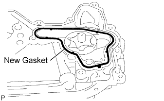
Install a new gasket to the timing gear case.
OIL PUMP (w/o EGR Cooler) > INSTALLATION |
| 1. INSTALL TIMING GEAR CASE ASSEMBLY |
Install 2 new O-rings to the cylinder block.
Remove any old seal packing (FIPG material) from the timing gear case and cylinder block.
|
Install a new gasket to the timing gear case.
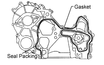 |
Apply seal packing as shown in the illustration.
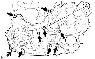 |
Install the timing gear case with union bolt A and the 8 bolts.
Make sure that the oil pump drive gear rotates smoothly.
If the gear does not rotate smoothly, loosen the 8 bolts and union bolt and turn the gear. Then tighten the 8 bolts and union bolt and check the gear again.
Install the No. 1 vacuum transmitting pipe with the nut.
| 2. INSTALL OIL STRAINER SUB-ASSEMBLY |
Install a new gasket and the oil strainer with the 2 bolts and nut.
| 3. INSTALL OIL PAN SUB-ASSEMBLY |
Remove any old seal packing (FIPG) from the oil pan and cylinder block.
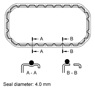 |
Apply seal packing as shown in the illustration.
Install the oil pan with the 22 bolts and 2 nuts.
| 4. INSTALL ENGINE OIL LEVEL DIPSTICK GUIDE |
Apply clean engine oil to a new O-ring.
Install the O-ring to the dipstick guide.
Install the dipstick guide with the bolt.
| 5. INSTALL ENGINE OIL LEVEL DIPSTICK |
| 6. INSTALL FUEL SUPPLY PUMP ASSEMBLY |
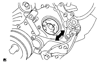 |
Check that the supply pump gear in the timing gear case moves back and forth smoothly.
Install a new O-ring to the pump.
Apply a light coat of engine oil to the O-ring.
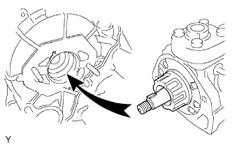 |
Align the set key on the drive shaft with the groove of the injection gear.
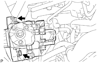 |
Install the pump with the 2 nuts.
Set a new O-ring before tightening the set nut.
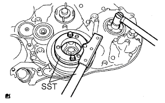 |
Using SST, hold the crankshaft pulley and install the set nut.
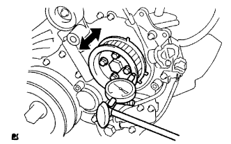 |
Move the pump drive shaft pulley back and forth to check the thrust clearance of the injection pump drive shaft.
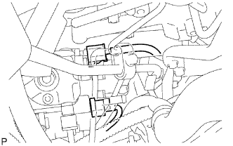 |
Connect the 2 connectors.
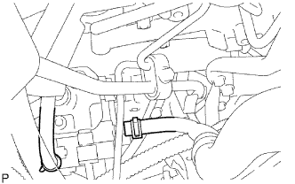 |
Connect the 2 fuel hoses.
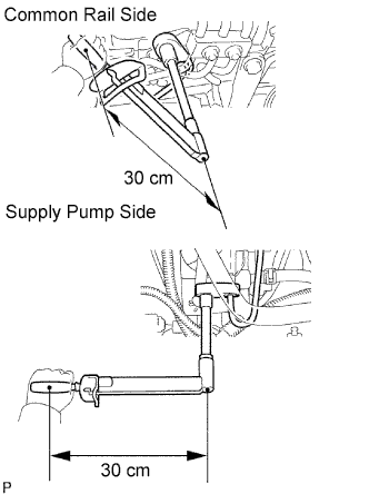 |
Temporarily install the fuel inlet pipe with the union nuts.
Using a 17 mm union nut wrench, tighten the injection pipe union nut on the common rail side.
Using a 17 mm union nut wrench, tighten the injection pipe union nut on the supply pump side.
Install the oil level gauge guide with the 2 bolts.
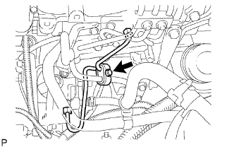 |
Install the clamp with the bolt.
| 7. INSTALL INJECTION GEAR |
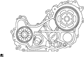 |
Install the injection gear and a new O-ring, and then temporarily install the nut. Using your hand, check the thrust clearance of the supply pump drive shaft by turning the injection gear.
| 8. INSTALL CRANKSHAFT TIMING GEAR |
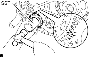 |
Align the "1" timing marks of the oil pump drive gear and crankshaft timing gear as shown in the illustration.
Using SST, install the crankshaft timing gear.
| 9. INSTALL NO. 1 IDLE GEAR |
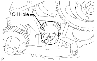 |
Install the No. 1 idle gear shaft to the cylinder block.
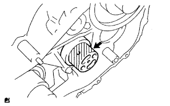 |
Apply a light coat engine oil to the No. 1 idle gear shaft shown in the illustration.
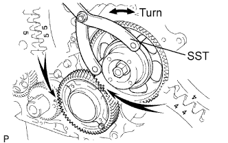 |
Align the "5" timing marks of the idle gear and crankshaft timing gear.
Using SST, turn the supply pump gear, and align the "4" timing marks of the idle gear and injection gear, and mesh the gears.
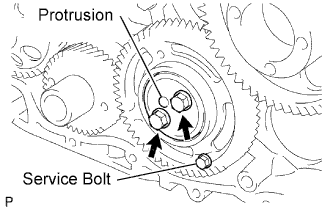 |
Temporarily install the No. 1 idle gear and idle gear thrust plate with the 2 bolts.
Secure the No. 2 idle gear to the No. 1 idle gear with a service bolt.
Tighten the 2 bolts.
Remove the service bolt.
Install the No. 1 crankshaft sensor plate.
| 10. INSTALL TIMING GEAR COVER |
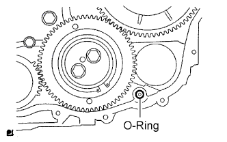 |
Install a new O-ring to the timing gear case.
Remove any old seal packing (FIPG material) from the timing gear cover.
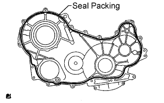 |
Apply seal packing as shown in the illustration.
Install the cover with the 14 bolts and 2 nuts.
Install the wire harness clamp.
| 11. INSTALL CRANKSHAFT POSITION SENSOR |
Install the crankshaft position sensor with the bolt.
| 12. INSTALL CAMSHAFT POSITION SENSOR |
Install the camshaft position sensor with the bolt.
| 13. INSTALL CRANKSHAFT PULLEY |
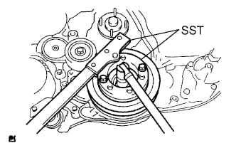 |
Align the pulley set key with the key groove of the pulley.
Using SST, install the pulley bolt.
| 14. INSTALL PUMP DRIVE SHAFT PULLEY |
Install a new O-ring to the supply pump.
Temporarily install the supply pump with the nut.
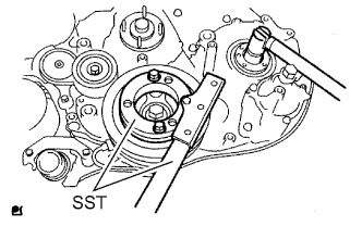 |
Using SST, hold the crankshaft pulley and tighten the nut.
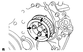 |
Install the No. 2 camshaft timing pulley flange and pump drive shaft pulley with the 4 bolts.
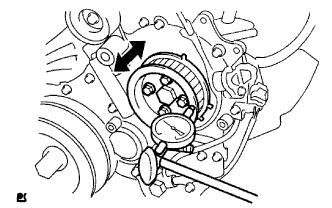 |
Using a dial indicator, check the thrust clearance of the pump drive shaft while moving the pump drive shaft pulley back and forth.
| 15. INSTALL VANE PUMP ASSEMBLY |
Install a new O-ring to the vane pump.
Install the vane pump with the 2 nuts.
| 16. INSTALL VACUUM PUMP ASSEMBLY |
Install 2 new O-rings to the vacuum pump.
Install the vacuum pump with the 2 nuts.
| 17. INSTALL WATER PUMP ASSEMBLY |
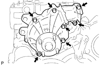 |
Install a new gasket and the water pump with the 5 bolts and 2 nuts.
| 18. INSTALL NO. 2 TIMING BELT COVER |
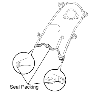 |
Apply seal packing (FIPG) to the specified areas shown in the illustration.
Install the No. 2 timing belt cover with the 4 bolts and nut.
| 19. INSTALL NO. 1 TIMING BELT IDLER SUB-ASSEMBLY |
| 20. INSTALL CAMSHAFT TIMING PULLEY |
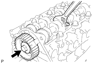 |
Install the camshaft timing pulley.
Fasten the bolt of the camshaft timing pulley by holding the camshaft with a wrench.
| 21. INSTALL CYLINDER HEAD COVER SUB-ASSEMBLY |
Remove any old seal packing (FIPG) material from the cylinder head.
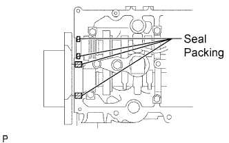 |
Apply seal packing to the specific areas shown in the illustration.
Install a new cylinder head cover gasket and the cylinder head cover with the 10 bolts and 2 nuts.
Install 4 new nozzle holder seals.
Connect the 4 injector connectors.
Connect the ventilation hose.
| 22. INSTALL FUEL INLET PIPE SUB-ASSEMBLY |
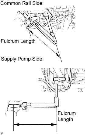 |
Temporarily install the fuel inlet pipe with the union nuts.
Using a 17 mm union nut wrench, tighten the fuel inlet pipe union nut on the common rail side.
Using a 17 mm union nut wrench, tighten the fuel inlet pipe union nut on the supply pump side.
Install a new O-ring to the engine oil level dipstick guide.
Install the engine oil level dipstick guide with the bolt.
Install the clamp with the bolt.
Install the engine oil level dipstick.
| 23. INSTALL NO. 4 INJECTION PIPE SUB-ASSEMBLY |
Temporarily install the No. 4 injection pipe with the union nuts.
Install the 2 bolts.
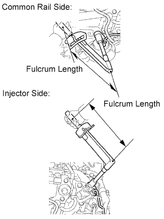 |
Using a 17 mm union nut wrench, tighten the injection pipe union nut on the common rail side.
Using a 17 mm union nut wrench, tighten the injection pipe union nut on the injector side.
| 24. INSTALL NO. 1 INJECTION PIPE SUB-ASSEMBLY |
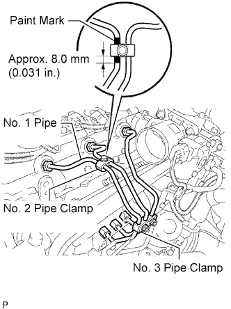 |
Temporarily install the No. 1, No. 2 and No. 3 injection pipes with the union nuts.
Install the No. 2 and No. 3 injection pipe clamps with the bolt and 2 nuts, as shown in the illustration.
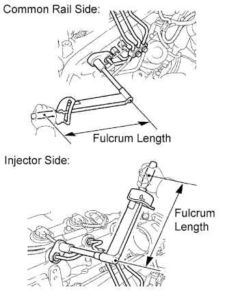 |
Using a 17 mm union nut wrench, tighten the injection pipe union nuts on the common rail side.
Using a 17 mm union nut wrench, tighten the injection pipe union nuts on the injector side.
| 25. INSTALL MANIFOLD STAY |
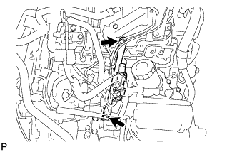 |
Install the stay with the 2 bolts.
Connect the 3 vacuum hoses to the 2 VSV.
| 26. INSTALL V-RIBBED BELT TENSIONER ASSEMBLY |
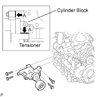 |
Install the V-ribbed belt tensioner with the 4 bolts.
| 27. INSTALL NO. 1 COMPRESSOR MOUNTING BRACKET |
Install the No. 1 compressor mounting bracket with the 4 bolts.
| 28. INSTALL GENERATOR BRACKET |
Install the generator bracket with the bolt.
| 29. INSTALL GENERATOR ASSEMBLY |
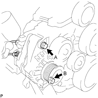 |
Install the generator with the 2 bolts.
Install the generator wire with the nut.
Connect the generator connector.
| 30. INSTALL NO. 2 IDLE PULLEY ASSEMBLY |
| 31. INSTALL NO. 1 VISCOUS HEATER BRACKET SUB-ASSEMBLY |
Install the No. 1 viscous heater bracket with the 2 bolts.
| 32. INSTALL VISCOUS WITH MAGNET CLUTCH HEATER ASSEMBLY |
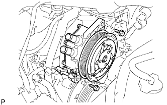 |
Install the viscous with magnet clutch heater with the 2 bolt.
Connect the connect.
| 33. INSTALL TIMING BELT |
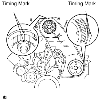 |
Check that the timing marks are aligned as shown in the illustration.
Using a 10 mm hexagon wrench, install the timing belt idler pulley and new washer with the bolt.
Check that the idler pulley moves smoothly.
If it does not move smoothly, check the idler sub-assembly and washer.
Install the timing belt to the pump drive shaft pulley, camshaft timing pulley and No. 1 timing belt idler in sequence.
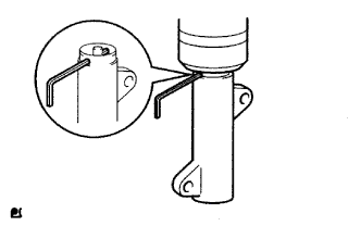 |
Place the tensioner upright. Then set the press to the top of the tensioner.
Using a press, slowly push in the push rod using 981 to 9,807 N (100 to 1,000 kgf, 220 to 2,205 lbf) of force.
Align the holes of the push rod and housing. Then pass a 1.27 mm hexagon wrench through the holes to keep the setting position of the push rod.
Install the timing belt tensioner with the 2 bolts while pushing the idler pulley toward the timing belt.
Tighten the 2 bolts.
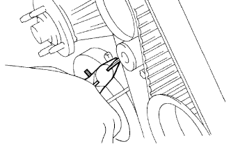 |
Remove the 1.5 mm hexagon wrench from the tensioner.
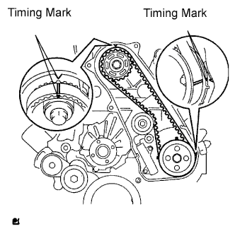 |
Turn the crankshaft clockwise 720° and check that the timing marks are aligned as shown in the illustration.
| 34. INSTALL NO. 1 TIMING BELT COVER |
Install the timing belt cover with the 6 bolts.
Install the wire harness clamp.
Install the water hose clamp with the bolt.
| 35. INSTALL ENGINE ASSEMBLY |
Install the engine (Click here).