Home › HEATER & AIR CONDITIONING SYSTEM › AIR CONDITIONING › AIR CONDITIONING SYSTEM (for Automatic Air Conditioning System)

DTC    21    Solar Sensor Circuit

for Preparation Click here


DESCRIPTION

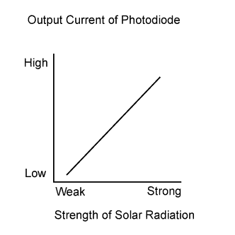
E132508E01
The solar sensor, which is installed on the upper side of the instrument panel, detects sunlight and controls the air conditioning in AUTO mode. The output current from the solar sensor varies according to the amount of sunlight. When the amount of sunlight increases, the output current increases. As the amount of sunlight decreases, the output current decreases. The air conditioning amplifier detects the output current from the solar sensor.

DTC Code
Detection Item
Trouble Area
21
Open or short in solar sensor circuit
(If check is performed in a dark place, DTC 21 may be stored)
  1. A/C solar sensor
  2. Harness or connector
  3. Air conditioning amplifier assembly

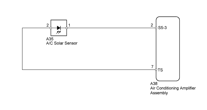
WIRING DIAGRAM


E171027E01


INSPECTION PROCEDURE

1.CHECK AIR CONDITIONING AMPLIFIER ASSEMBLY (TS VOLTAGE)


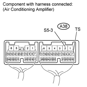
    E170950E03
  1. Remove the air conditioning amplifier with its connectors still connected.

  1. Measure the voltage according to the value(s) in the table below.

Standard Voltage:
Tester Connection
Switch Condition
Specified Condition
A38-2 (S5-3) - A38-7 (TS)
Ignition switch ON
Sensor subjected to electric light
0.8 to 4.3 V
Ignition switch ON
Sensor covered with a cloth
Below 0.8 V

HINT:
  1. As the inspection light is moved away from the sensor, the voltage decreases.
  2. Use an incandescent light for inspection. Bring it within 30 cm (11.8 in.) of the A/C solar sensor.


NG
Go to step 2
OK

REPLACE AIR CONDITIONING AMPLIFIER ASSEMBLY (Click here)  

2.INSPECT A/C SOLAR SENSOR


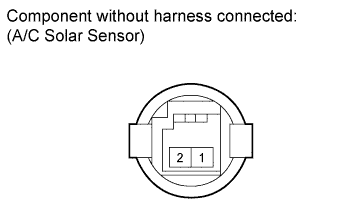
    E170951E01
  1. Remove the solar sensor.

  1. Measure the resistance according to the value(s) in the table below.

    1. Connect the ohmmeter's negative (-) lead to terminal 1 and positive (+) lead to terminal 2.

      Standard Resistance:
      Tester Connection
      Condition
      Specified Condition
      1 - 2
      Sensor is subjected to electric light
      Below 10 kΩ
      Sensor is covered with a cloth
      10 kΩ or higher

      NOTICE:
      The connection procedure for a digital tester, such as a TOYOTA electrical tester, is shown above. When using an analog tester, connect the negative (-) lead to terminal 2 and positive (+) lead to terminal 1.

      HINT:
      1. As the inspection light is moved away from the sensor, the resistance increases.
      2. Use an incandescent light for inspection. Bring it within 30 cm (11.8 in.) of the A/C solar sensor.


NG
REPLACE A/C SOLAR SENSOR (Click here)
OK


3.CHECK HARNESS AND CONNECTOR (A/C SOLAR SENSOR - AIR CONDITIONING AMPLIFIER)


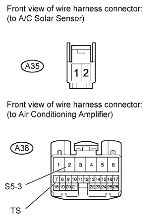
    E170942E09
  1. Disconnect the A35 sensor connector.

  1. Disconnect the A38 amplifier connector.

  1. Measure the resistance according to the value(s) in the table below.

    Standard Resistance:
    Tester Connection
    Condition
    Specified Condition
    A38-2 (S5-3) - A35-1
    Always
    Below 1 Ω
    A38-7 (TS) - A35-2
    A38-2 (S5-3) - Body ground
    Always
    10 kΩ or higher
    A38-7 (TS) - Body ground


NG
REPAIR OR REPLACE HARNESS OR CONNECTOR
OK

REPLACE AIR CONDITIONING AMPLIFIER ASSEMBLY (Click here)