 |
Connect an intelligent tester to the DLC3.
DTC P2009 Intake Manifold Runner Control Circuit Low (Bank 1) |
DTC P2010 Intake Manifold Runner Control Circuit High (Bank 1) |
| DTC No. | DTC Detection Condition | Trouble Area |
| P2009 | Open in VSV for swirl control valve circuit for 0.5 seconds (2 trip detection logic) |
|
| P2010 | Short in VSV for swirl control valve circuit for 0.5 seconds (2 trip detection logic) |
|
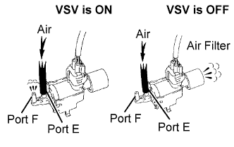
| 1.PERFORM ACTIVE TEST USING INTELLIGENT TESTER (ACTIVATE THE VACUUM SWITCHING VALVE FOR SWIRL CONTROL VALVE) |
|
Connect an intelligent tester to the DLC3.
Disconnect the vacuum hoses from the VSV for swirl control valve.
Turn the ignition switch ON and turn the tester ON.
Select the following menu items: Powertrain / Engine and ECT / Active Test / Activate the VSV for Swirl Control Valve.
Check the operation.
|
| ||||
| NG | |
 |
| 2.INSPECT VACUUM SWITCHING VALVE FOR SWIRL CONTROL VALVE (RESISTANCE) |
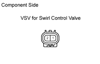 |
Disconnect the S9 vacuum hoses from the VSV for swirl control valve connector.
Measure the resistance of the VSV.
| Tester Connection | Condition | Specified Condition |
| 1 - 2 | 20°C (68°F) | 37 to 44 Ω |
|
| ||||
| OK | |
|
| 3.INSPECT VACUUM SWITCHING VALVE FOR SWIRL CONTROL VALVE (POWER SOURCE VOLTAGE) |
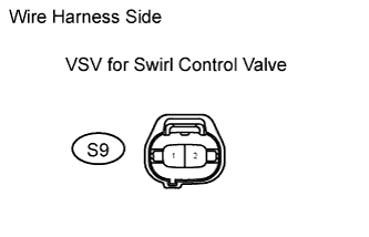 |
Disconnect the S9 vacuum hoses from the VSV for swirl control valve connector.
Turn the ignition switch ON.
Measure the voltage between the terminal of the wire harness side connector and body ground.
| Tester Connection | Specified Condition |
| VSV for swirl control valve (S9-1) - Body ground | 11 to 14 V |
|
| ||||
| NG | |
|
| 4.CHECK HARNESS AND CONNECTOR (INTEGRATION RELAY (MAIN RELAY) - VACUUM SWITCHING VALVE FOR SWIRL CONTROL VALVE) |
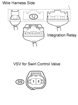 |
Remove the integration relay from the engine room junction block (Click here).
Disconnect the 1J integration relay connector.
Disconnect the S9 VSV connector.
Measure the resistance of the wire harness side connectors.
| Tester Connections | Specified Conditions |
| 1J-5 - S9-2 | Below 1 Ω |
| Tester Connections | Specified Conditions |
| 1J-5 or S9-2 - Body ground | 10 kΩ or higher |
|
| ||||
| OK | ||
 | ||
| ||
| 5.CHECK HARNESS AND CONNECTOR (VACUUM SWITCHING VALVE FOR SWIRL CONTROL VALVE - ECM) |
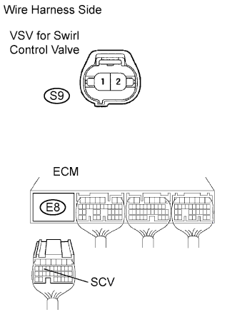 |
Disconnect the S9 VSV connector.
Disconnect the E6 ECM connector.
Check the resistance.
| Tester Connection | Specified Condition |
| S9-1 - E8-15 (SCV) | Below 1 Ω |
| Tester Connection | Specified Condition |
| S9-1 or E8-15 (SCV) - Body ground | 10 kΩ or higher |
|
| ||||
| OK | ||
| ||
| ||

