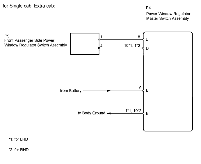
POWER WINDOW CONTROL SYSTEM > Remote Up / Down Function does not Operate |
| 1.CHECK POWER WINDOW REGULATOR MASTER SWITCH ASSEMBLY |
 |
Turn the window lock switch OFF and operate the switches on the master switch. Check that the remote UP / DOWN function operates normally.
|
| ||||
| OK | ||
 | ||
| ||
| 2.CHECK MANUAL UP / DOWN FUNCTION |
Check that the front passenger door power window and rear door power window manual UP / DOWN function operates normally.
|
| ||||
| OK | |
 |
| 3.CHECK WIRE HARNESS (MASTER SWITCH - FRONT PASSENGER SIDE SWITCH) |
for Single cab, Extra cab:
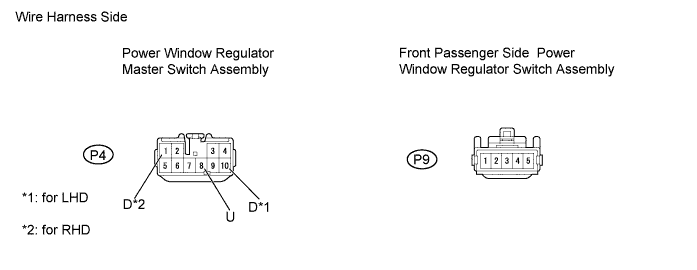
Disconnect the P4 master switch connector.
Disconnect the P9 switch connector.
Measure the resistance of the wire harness side connectors.
| Tester Connection | Specified Condition |
| P4-8 (U) - P9-1 | Below 1 Ω |
| P4-10 (D) - P9-4 | Below 1 Ω |
| P4-8 (U) or P9-1 Body ground | 10 kΩ or higher |
| P4-10 (D) or P9-4 Body ground | 10 kΩ or higher |
| Tester Connection | Specified Condition |
| P4-8 (U) - P9-1 | Below 1 Ω |
| P4-1 (D) - P9-4 | Below 1 Ω |
| P4-8 (U) or P9-1 Body ground | 10 kΩ or higher |
| P4-1 (D) or P9-4 Body ground | 10 kΩ or higher |
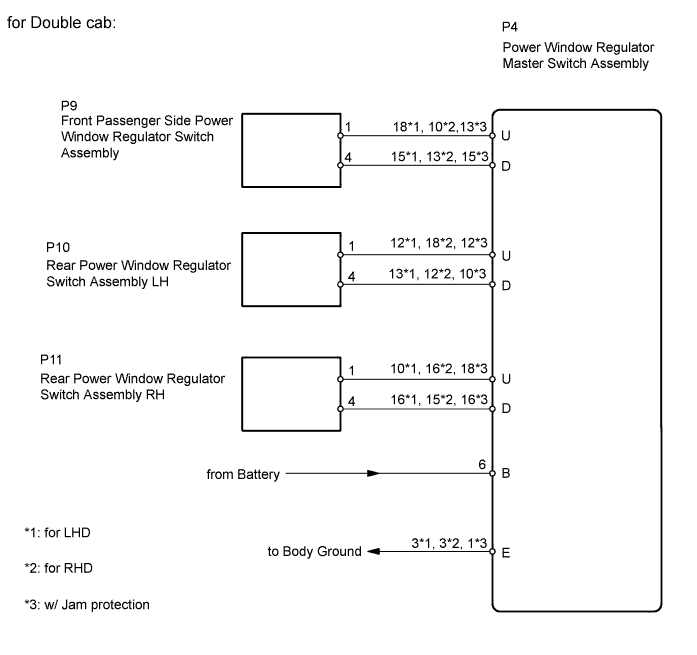
for Double cab:
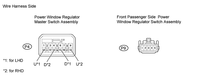
Disconnect the P4 master switch connector.
Disconnect the P9 switch connector.
Measure the resistance of the wire harness side connectors.
| Tester Connection | Specified Condition |
| P4-18 (U) - P9-1 | Below 1 Ω |
| P4-15 (D) - P9-4 | Below 1 Ω |
| P4-18 (U) or P9-1 Body ground | 10 kΩ or higher |
| P4-15 (D) or P9-4 Body ground | 10 kΩ or higher |
| Tester Connection | Specified Condition |
| P4-10 (U) - P9-1 | Below 1 Ω |
| P4-13 (D) - P9-4 | Below 1 Ω |
| P4-10 (U) or P9-1 Body ground | 10 kΩ or higher |
| P4-13 (D) or P9-4 Body ground | 10 kΩ or higher |
w/ Jam protection:
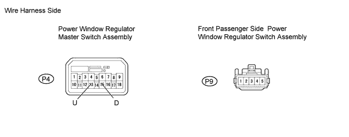
Disconnect the P4 master switch connector.
Disconnect the P9 switch connector.
Measure the resistance of the wire harness side connectors.
| Tester Connection | Specified Condition |
| P4-13 (U) - P9-1 | Below 1 Ω |
| P4-15 (D) - P9-4 | Below 1 Ω |
| P4-13 (U) or P9-1 Body ground | 10 kΩ or higher |
| P4-15 (D) or P9-4 Body ground | 10 kΩ or higher |
| Result | Proceed to |
| OK (for Single cab, Extra cab) | A |
| OK (for Double cab) | B |
| NG | C |
|
| ||||
|
| ||||
| A | ||
| ||
| ||
| 4.CHECK WIRE HARNESS (MASTER SWITCH - REAR SWITCH LH) |
w/o Jam Protection:
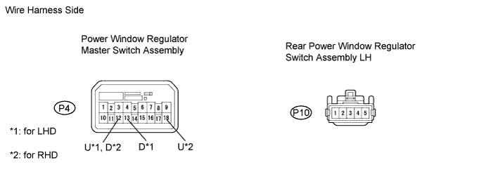
Disconnect the P4 master switch connector.
Disconnect the P10 switch connector.
Measure the resistance of the wire harness side connectors.
| Tester Connection | Specified Condition |
| P4-12 (U) - P10-1 | Below 1 Ω |
| P4-13 (D) - P10-4 | Below 1 Ω |
| P4-12 (U) or P10-1 Body ground | 10 kΩ or higher |
| P4-13 (D) or P10-4 Body ground | 10 kΩ or higher |
| Tester Connection | Specified Condition |
| P4-18 (U) - P10-1 | Below 1 Ω |
| P4-12 (D) - P10-4 | Below 1 Ω |
| P4-18 (U) or P10-1 Body ground | 10 kΩ or higher |
| P4-12 (D) or P10-4 Body ground | 10 kΩ or higher |
w/ Jam protection
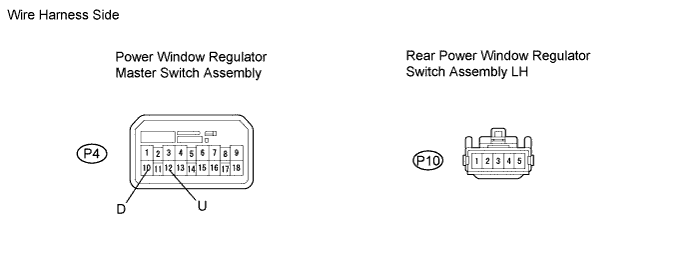
Disconnect the P4 master switch connector.
Disconnect the P10 switch connector.
Measure the resistance of the wire harness side connectors.
| Tester Connection | Specified Condition |
| P4-12 (U) - P10-1 | Below 1 Ω |
| P4-10 (D) - P10-4 | Below 1 Ω |
| P4-12 (U) or P10-1 Body ground | 10 kΩ or higher |
| P4-10 (D) or P10-4 Body ground | 10 kΩ or higher |
|
| ||||
| OK | |
|
| 5.CHECK WIRE HARNESS (MASTER SWITCH - REAR SWITCH RH) |
w/o Jam Protection:
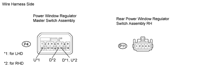
Disconnect the P4 master switch connector.
Disconnect the P11 switch connector.
Measure the resistance of the wire harness side connectors.
| Tester Connection | Specified Condition |
| P4-10 (U) - P11-1 | Below 1 Ω |
| P4-16 (D) - P11-4 | Below 1 Ω |
| P4-10 (U) or P11-1 Body ground | 10 kΩ or higher |
| P4-16 (D) or P11-4 Body ground | 10 kΩ or higher |
| Tester Connection | Specified Condition |
| P4-16 (U) - P11-1 | Below 1 Ω |
| P4-15 (D) - P11-4 | Below 1 Ω |
| P4-16 (U) or P11-1 Body ground | 10 kΩ or higher |
| P4-15 (D) or P11-4 Body ground | 10 kΩ or higher |
w/ Jam protection
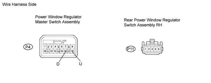
Disconnect the P4 master switch connector.
Disconnect the P11 switch connector.
Measure the resistance of the wire harness side connectors.
| Tester Connection | Specified Condition |
| P4-18 (U) - P11-1 | Below 1 Ω |
| P4-16 (D) - P11-4 | Below 1 Ω |
| P4-18 (U) or P11-1 Body ground | 10 kΩ or higher |
| P4-16 (D) or P11-4 Body ground | 10 kΩ or higher |
|
| ||||
| OK | ||
| ||
| ||

