Home › INTRODUCTION › INTRODUCTION › REPAIR INSTRUCTION

REPAIR INSTRUCTION > INITIALIZATION


System Name
ECD System
Vehicle Stability Control System
Power Window Control System
Meter / Gauge System

INITIALIZATION RELATED TO ECD SYSTEM

HINT:
After replacing the supply pump and/or ECM:

  1. If the engine is defective or stalls immediately after startup, the ECM's learned values must be initialized. The engine can be initialized through the intelligent tester or by short circuit DLC3 terminals.
  2. If the engine starts normally, initialization is not necessary. Perform procedure "A" and procedure "B" only.


  1. SUPPLY PUMP INITIALIZATION PROCEDURE


      A141744E01
    1. Connect the intelligent tester to the DLC3.

    2. Turn the ignition switch ON.

      NOTICE:
      Do not start the engine.

    3. Turn the intelligent tester ON.

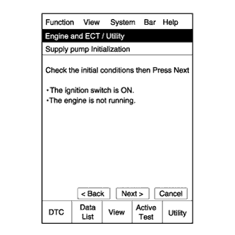
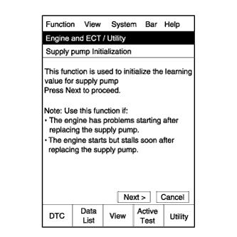
    4. Enter the following menus: Powertrain / Engine / Utility / Supply Pump Initialization.

    5. Press Next.


    6. A141745E01
    7. Press Next.


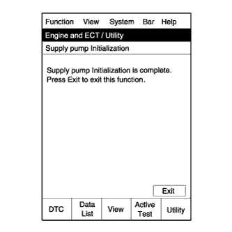
    8. A141746E01
    9. Press Exit.

    10. Start the engine to check if the initialization is complete. If the engine cannot be started, repeat the initialization procedures from the beginning.

    11. Idle the engine for at least 1 minute under the following conditions (Procedure "A"):

      1. The water temperature is 60°C (140°F) or more.
      2. The fuel temperature is 20°C (68°F) or more.

      NOTICE:
      1. Do not the race engine immediately after starting the engine.
      2. After idling the engine, racing the engine is acceptable.

        HINT:
        1. The water temperature can be estimated by touching the outlet hose.
        2. The fuel temperature can be estimated by using the ambient temperature as a substitute.
        3. If the water and fuel temperature is difficult to estimate, use the intelligent tester and enter the following menus: Powertrain / Engine / Data List / Coolant Temp.

    12. Initialization is complete (Procedure "B").

CALIBRATION RELATED TO VEHICLE STABILITY CONTROL SYSTEM
  1. DESCRIPTION

    1. Follow the chart below to perform calibration.

      Parts to be Replaced / Operation
      Necessary Operation
      Skid control ECU (Brake actuator assembly)
      Yaw rate and acceleration sensor zero point calibration
      Yaw rate and acceleration sensor
      1. Clearing zero point calibration data
      2. Yaw rate and acceleration sensor zero point calibration
      Front wheel alignment adjustment
      1. Clearing zero point calibration data
      2. Yaw rate and acceleration sensor zero point calibration

  2. OBTAIN ZERO POINT OF YAW RATE AND ACCELERATION SENSOR (When Using Intelligent Tester)

    NOTICE:
    1. While obtaining the zero points, keep the vehicle stationary and do not vibrate, tilt, move, or shake it. (Do not start the engine.)
    2. Be sure to perform this procedure on a level surface (with an inclination of less than 1 degree).


    1. Clear the zero point calibration data.

      1. Turn the ignition switch off.
      2. Check that the steering wheel is in the straight-ahead position.
      3. for A/T:
        Check that the shift lever is in the P position and apply the parking brake.
      4. for M/T:
        Check that the shift lever is in neutral and apply the parking brake.
      5. Connect the intelligent tester to the DLC3.
      6. Turn the ignition switch to ON.
      7. Turn the intelligent tester on.
      8. Select the skid control ECU to clear the zero point calibration data using the intelligent tester. Enter the following menus: Chassis / ABS/VSC/TRC / Reset Memory.
      9. Turn the ignition switch off.

    2. Perform the zero point calibration of the yaw rate and acceleration sensor.

      1. Turn the ignition switch off.
      2. Check that the steering wheel is in the straight-ahead position.
      3. for A/T:
        Check that the shift lever is in the P position and apply the parking brake.
      4. for M/T:
        Check that the shift lever is in neutral and apply the parking brake.

        NOTICE:
        DTCs C1210 (zero point calibration of yaw rate sensor undone) and C1336 (zero point calibration of acceleration sensor undone) will be recorded if the shift lever is not in the P position (for A/T) or the parking brake is not applied (for M/T).

      5. Connect the intelligent tester to the DLC3.
      6. Turn the ignition switch to ON.
      7. Turn the intelligent tester on.
      8. Switch the skid control ECU to Test Mode using the intelligent tester. Enter the following menus: Chassis / ABS/VSC/TRC / Test Mode.
      9. After Test Mode has been entered, keep the vehicle stationary on a level surface for 2 seconds or more.

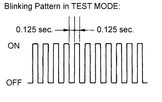
      10. BR03904E80
        Check that the VSC OFF indicator light comes on for several seconds and then blinks in Test Mode.

        HINT:
        1. If the VSC OFF indicator light does not blink, perform zero point calibration again.
        2. The zero point calibration is performed only once after the system enters Test Mode.
        3. Calibration cannot be performed again until the stored data is cleared.

      11. Turn the ignition switch off and disconnect the intelligent tester.

  3. OBTAIN ZERO POINT OF YAW RATE AND ACCELERATION SENSOR (When not Using Intelligent Tester)

    NOTICE:
    1. While obtaining the zero points, keep the vehicle stationary and do not vibrate, tilt, move, or shake it. (Do not start the engine.)
    2. Be sure to perform this procedure on a level surface (with an inclination of less than 1 degree).


    1. Clear the zero point calibration data.

      1. Turn the ignition switch off.
      2. Check that the steering wheel is in the straight-ahead position.
      3. for A/T:
        Check that the shift lever is in the P position and apply the parking brake.
      4. for M/T:
        Check that the shift lever is in neutral and apply the parking brake.
      5. Turn the ignition switch to ON.
      6. The warning light and indicator light come on for 3 seconds to indicate that the initial check is completed.

      7. C166029
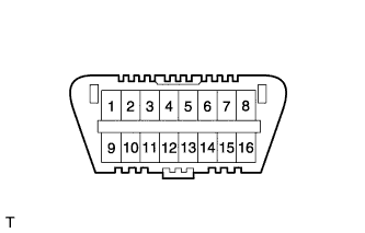
        Using SST, connect and disconnect terminals 12 (TS) and 4 (CG) of the DLC3 4 times or more within 8 seconds.

        SST:
        09843-18040

      8. Check that the VSC OFF indicator light comes on.

    2. Perform the zero point calibration of the yaw rate and acceleration sensor.

      1. Turn the ignition switch off.
      2. Check that the steering wheel is in the straight-ahead position.
      3. for A/T:
        Check that the shift lever is in the P position and apply the parking brake.
      4. for M/T:
        Check that the shift lever is in neutral and apply the parking brake.

        NOTICE:
        DTCs 36 (zero point calibration of yaw rate sensor undone) and 39 (zero point calibration of acceleration sensor undone) will be recorded if the shift lever is not in the P position (for A/T) or the parking brake is not applied (for M/T).


      5. C166029
        Using SST, connect terminals 12 (TS) and 4 (CG) of the DLC3.

        SST:
        09843-18040

      6. Turn the ignition switch to ON.
      7. After Test Mode has been entered, keep the vehicle stationary on a level surface for 2 seconds or more.

      8. BR03904E80
        Check that the VSC OFF indicator light comes on for several seconds and then blinks in Test Mode.

        HINT:
        1. If the VSC OFF indicator light does not blink, perform zero point calibration again.
        2. The zero point calibration is performed only once after the system enters Test Mode.
        3. Calibration cannot be performed again until the stored data is cleared.

      9. Turn the ignition switch off and disconnect SST from the DLC3.


RESET (INITIALIZE) POWER WINDOW REGULATOR MOTOR (for Driver Side)

NOTICE:
Resetting the power window regulator motor (initializing the pulse sensor) is necessary if one of the following occurs: 1) the battery cable is disconnected; 2) the power window regulator master switch, wire harness, power window regulator switch, power window regulator or power window regulator motor is replaced or removed / installed; or 3) the ALT H-fuse, AM1 H-fuse, IG1 H-fuse, PWR H-fuse, DOOR fuse, ECU-IG & GAUGE fuse or IG1 relay is replaced. If resetting is not performed, the master switch will not be able to operate the AUTO UP / DOWN function and jam protection function.

  1. Turn the ignition switch ON.

  2. Open the power window halfway by pressing the power window switch.

  3. Fully pull up on the switch until the power window is fully closed and continue to hold the switch for at least 1 second.

  4. Check that the AUTO UP / DOWN function operates normally.
    If the AUTO UP / DOWN function operates normally, reset operations are completed. If abnormal, follow the 3 steps below.

  5. Disconnect the cable from the negative (-) battery terminal for 10 seconds.

  6. Connect the cable to the negative (-) battery terminal.

  7. Perform the first 4 steps again.
    If the AUTO UP / DOWN function operates normally, reset operations have been completed at this time. If abnormal, follow the 4 steps below.

  8. Turn the ignition switch ON.

  9. Open the power window halfway by pressing the power window switch.

  10. Fully pull up on the switch until the power window is fully closed and continue to hold the switch for approximately 12 seconds after the power window is fully closed.

  11. Check that the AUTO UP / DOWN function operates normally.


RESET COMPASS IN COMBINATION METER

CAUTION:
  1. Strictly observe posted speed limits, traffic laws and road conditions.
  2. Make sure no people are near the vehicle.

NOTICE:
  1. Perform the circling calibration in a spacious area that does not have artificial magnetic influence. For example, underground parking lots, areas under a steel tower and areas between tall buildings are not acceptable.
  2. When performing calibration, do not operate the air conditioner, power windows, or any other electrical equipment.
  3. A compass may become magnetized during shipping by vessels or freight cars. Make sure to perform calibration and ensure that the calibration is performed properly. If calibration cannot be completed in spite of performing the circling calibration described below, the vehicle's magnetic field may be interfering with the calibration. Demagnetize the vehicle using a demagnetizer and perform calibration again.

  1. Circling calibration

    1. Select compass mode.

    2. Press and hold INFO for 3 seconds to enter the compass correction mode.

    3. Press RESET.

    4. Drive the vehicle slowly in a circle once within 128 seconds.

      HINT:
      1. If the circling calibration is completed, the correct direction is displayed automatically.
      2. If the correct direction is not displayed after driving the vehicle as specified, change the vehicle location.

    5. If there is not enough space to drive in a circle, perform the following:

      1. Drive the vehicle forward with the steering wheel fully turned to the right, and then drive in reverse with the steering wheel fully turned to the left.
      2. Repeat the pattern above 2 times within 128 seconds.

      HINT:
      1. If the circling calibration is completed, the correct direction is displayed automatically.
      2. If the correct direction is not displayed after driving the vehicle as specified, change the vehicle location.

  2. Compass correction mode cancellation

    1. Press RESET after performing the circling calibration.

    2. Press INFO or wait for 6 seconds to end the compass correction mode.


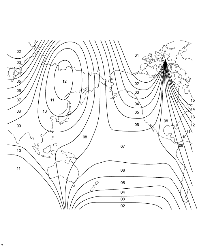
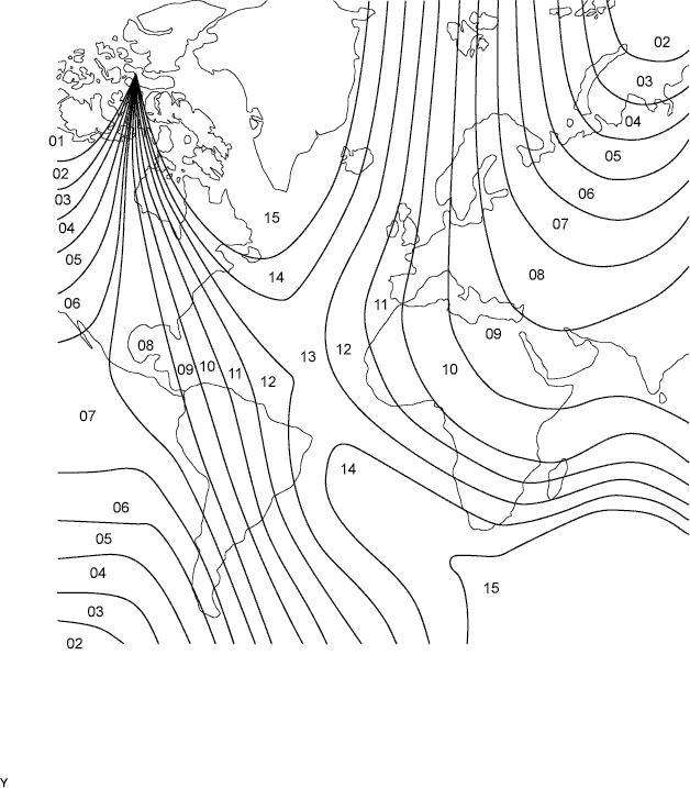
  3. Zone setting

    1. Select compass mode.

    2. Press and hold INFO for 3 seconds to enter compass correction mode.

    3. Press H to select a higher zone number.

    4. Press M to select a lower zone number.


    5. Press INFO or wait for 6 seconds to end compass correction mode.


      E110247E01


      E110246E01