METER / GAUGE SYSTEM > ON-VEHICLE INSPECTION |
| 1. CHECK SPEEDOMETER |
Check operation.
Using a speedometer tester, check that the speedometer reading is within the allowable range shown in the table below. Also, check for proper operation of the odometer.
| Standard Indication | Allowable Range |
| 20 km/h | 17.5 to 21.5 km/h |
| 40 km/h | 38 to 42 km/h |
| 60 km/h | 58 to 63 km/h |
| 80 km/h | 78 to 84 km/h |
| 100 km/h | 98 to 104.5 km/h |
| 120 km/h | 119 to 125 km/h |
| 140 km/h | 141 to 146 km/h |
| 160 km/h | 159 to 167 km/h |
| 180 km/h | 179 to 188 km/h |
| Standard Indication | Allowable Range |
| 20 km/h | 21 to 25 km/h |
| 40 km/h | 41.7 to 46.2 km/h |
| 60 km/h | 62.7 to 67.2 km/h |
| 80 km/h | 83.4 to 88.4 km/h |
| 100 km/h | 104.3 to 109.3 km/h |
| 120 km/h | 125.1 to 130.6 km/h |
| 140 km/h | 145.8 to 151.8 km/h |
| 160 km/h | 166.2 to 173.2 km/h |
| 180 km/h | 186.9 to 194.5 km/h |
| Standard Indication | Allowable Range |
| 20 mph | 21.0 to 23.5 mph |
| 40 mph | 42.0 to 44.5 mph |
| 60 mph | 62.5 to 66.0 mph |
| 80 mph | 83.1 to 87.1 mph |
| 100 mph | 103.9 to 108.4 mph |
Check the deflection width of the speedometer indicator.
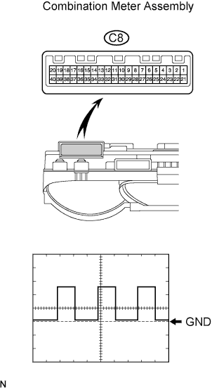
| 2. CHECK OUTPUT SIGNAL OF VEHICLE SPEED SENSOR |
|
Check the output signal waveform.
Remove the combination meter, but do not disconnect the connector.
Using an oscilloscope, check the waveform of the combination meter.
| Item | Content |
| Tester Connection | C8-6 - C8-22 |
| Tool Setting | 5 V/DIV., 20 msec./DIV. |
| Vehicle Condition | Vehicle running |
| 3. CHECK TACHOMETER |
Check operation.
Connect a tune-up test tachometer, and start the engine.
Compare the test tachometer values and vehicle tachometer values under the following conditions:
| Standard Tachometer Indication (rpm) | Acceptable Range (rpm) Data in ( ) are for reference only |
| 700 | 630 to 770 |
| 1,000 | (900 to 1,100) |
| 2,000 | (1,850 to 2,150) |
| 3,000 | 2,800 to 3,200 |
| 4,000 | (3,800 to 4,200) |
| 5,000 | 4,800 to 5,200 |
| 4. CHECK FUEL SUCTION WITH PUMP AND GAUGE TUBE ASSEMBLY |
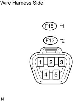 |
Disconnect the F15*1 or F13*2 pump and gauge connector.
Turn the ignition switch ON, and then check the position of the receiver gauge needle.
Connect terminals 2 and 3 of the wire harness side connector.
Turn the ignition switch ON, and then check the position of the receiver gauge needle.
| 5. CHECK FUEL LEVEL WARNING LIGHT |
|
Disconnect the F15*1 or F13*2 pump and gauge connector.
Turn the ignition switch ON, and then check that the fuel receiver gauge indicates E and that the fuel level warning light turns on.
| 6. CHECK LOW OIL PRESSURE WARNING LIGHT |
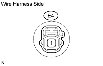 |
Disconnect the E4 switch connector.
Connect terminal 1 of the wire harness side connector to the body ground.
Turn the ignition switch ON, and then check that the low oil pressure warning light turns on.
| 7. CHECK BRAKE WARNING LIGHT |
 |
Check the parking brake warning light.
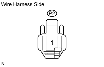
Disconnect the P2 switch connector.
Connect terminal 1 of the wire harness side connector to the body ground.
Turn the ignition switch ON, and then check that the warning light turns on.
 |
Check the brake fluid level warning light.
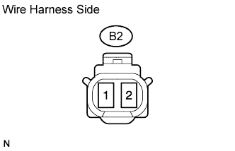
Disconnect the B2 switch connector.
Connect terminals 1 and 2 of the wire harness side connector.
Turn the ignition switch ON, and then check that the warning light turns on.
1KD-FTV, 2KD-FTV, 5L-E:
Check the vacuum pump warning light.
Disconnect the B3 switch connector.
Connect terminal 1 of the wire harness side connector to the body ground.
Turn the ignition switch ON, and then check that the warning light turns on.
| 8. CHECK SEAT BELT WARNING LIGHT FOR PASSENGER SIDE |
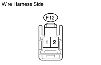 |
Disconnect the F12 switch connector.
Connect terminals 1 and 2 of the wire harness side connector.
Turn the ignition switch ON, and then check that the warning light blinks.