Home › TRANSMISSION · A343E AUTOMATIC TRANSMISSION › AUTOMATIC TRANSMISSION SYSTEM

DTC    P0756    Shift Solenoid "B" Performance (Shift Solenoid Valve S2)

for Preparation Click here


DESCRIPTION

The ECM uses signals from the speed sensor (NC0) and speed sensor (SP2) to detect the actual gear position (1st, 2nd, 3rd or 4th gear).
Then the ECM compares the actual gear position with the shift schedule in the ECM memory to detect mechanical problems of the shift solenoid valves, valve body or automatic transmission (clutch, brake or gear etc.).

DTC Code
DTC Detection Condition
Trouble Area
P0756
Gear required by ECM does not match actual gear when driving (2 trip detection logic)
  1. Shift solenoid valve S2 remains open or closed
  2. Valve body is blocked
  3. Shift solenoid valve S2
  4. Automatic transmission (clutch, brake or gear etc.)
  5. ECM

MONITOR DESCRIPTION

The ECM commands gear shifts by turning the shift solenoid valves "on/off". According to the input shaft revolution, intermediate (counter) shaft revolution and output shaft revolution, the ECM detects the actual gear position (1st, 2nd, 3rd or 4th gear). When the gear position commanded by the ECM and the actual gear position are not the same, the ECM illuminates the MIL and stores the DTC.

INSPECTION PROCEDURE

1.CHECK DTC OUTPUT (IN ADDITION TO DTC P0756)
  1. Connect the intelligent tester to the DLC3.

  1. Turn the ignition switch to ON and push the intelligent tester main switch on.

  1. Enter the following menus: Powertrain / ECT / DTC / Current or Pending.

  1. Read the DTCs using the intelligent tester.

    Result:
    Display (DTC output)
    Proceed to
    Only P0756 is output
    A
    P0756 and other DTCs are output
    B

    HINT:
    If any other codes besides P0756 are output, perform troubleshooting for those DTCs first.


B
GO TO DTC CHART
A


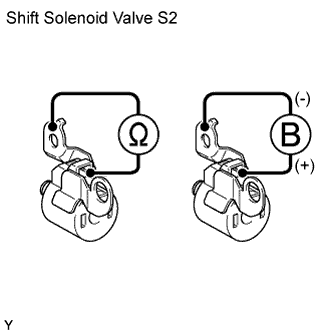
2.INSPECT SHIFT SOLENOID VALVE S2


    C155227E05
  1. Remove the shift solenoid valve S2.

  1. Measure the resistance of the solenoid value.

    Standard Resistance:
    Tester Connection
    Condition
    Specified Condition
    Shift solenoid S2 connector - Shift solenoid S2 body
    20°C (68°F)
    11 to 15 Ω

  1. Connect the battery's positive (+) lead to the terminal of the solenoid connector, and the negative (-) lead to the solenoid body.

  1. Check the operating noise of the solenoid valve.

    OK:
    Solenoid makes operating noise.


NG
REPLACE SHIFT SOLENOID VALVE S2
OK


3.INSPECT TRANSMISSION VALVE BODY ASSEMBLY
  1. Check the transmission valve body assembly.

    OK:
    There are no foreign objects on any valve.


NG
REPAIR OR REPLACE TRANSMISSION VALVE BODY ASSEMBLY
OK

REPAIR OR REPLACE AUTOMATIC TRANSMISSION ASSEMBLY