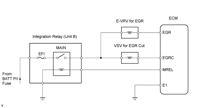
ECD SYSTEM (w/o EGR Cooler) > EGR Control Circuit |
| 1.CHECK CONNECTION OF VACUUM HOSE |
Check the connection of vacuum hose.
|
| ||||
| OK | |
 |
| 2.CHECK VACUUM |
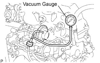 |
Using a 3-way connector, connect a vacuum gauge to the vacuum hose between the E-VRV for EGR and EGR valve.
Warm up the engine to above 80°C (176°F).
Check the vacuum at 1,500 rpm.
| Vacuum | Proceed to |
| 0 kPa (0 mmHg, 0 in.Hg) | A |
| 0 kPa (0 mmHg, 0 in.Hg) to 28 kPa (210 mmHg, 8.3 in.Hg) | B |
| Above 28 kPa (210 mmHg, 8.3 in.Hg) | C |
|
| ||||
|
| ||||
| B | |
|
| 3.PERFORM ACTIVE TEST USING INTELLIGENT TESTER (VACUUM SWITCHING VALVE FOR EGR CUT) |
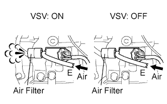 |
Disconnect the vacuum hose from the VSV.
Connect the intelligent tester to the DLC3.
Turn the ignition switch ON and turn the intelligent tester II ON.
Enter the following menus: Powertrain / Engine / Active Test / Activate the VSV for EGR Cut.
Check the operation.
|
| ||||
| NG | |
|
| 4.INSPECT VACUUM SWITCHING VALVEFOR EGR CUT |
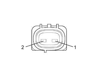 |
Disconnect the V2 VSV connector.
Measure the resistance of the VSV.
| Tester Connection | Condition | Specified Condition |
| 1 - 2 | 20°C (68°F) | 37 to 44 Ω |
|
| ||||
| OK | |
|
| 5.CHECK WIRE HARNESS (VACUUM SWITCHING VALVE FOR EGR CUT - ECM) |
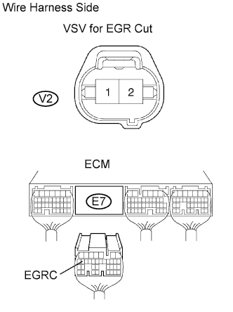 |
Disconnect the V2 VSV connector.
Disconnect the E7 ECM connector.
Measure the resistance of the wire harness side connectors.
| Tester Connection | Specified Condition |
| E7-18 (EGRC) - V2-2 | Below 1 Ω |
| E7-18 (EGRC) or V2-2 - Body ground | 10 kΩ or higher |
|
| ||||
| OK | |
|
| 6.CHECK WIRE HARNESS (VACUUM SWITCHING VALVE FOR EGR CUT - INTEGRATION RELAY (MAIN RELAY)) |
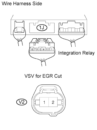 |
Remove the integration relay from the engine room junction block .
Disconnect the 1J integration relay connector.
Disconnect the V2 VSV connector.
Measure the resistance of the wire harness side connectors.
| Tester Connection | Specified Condition |
| 1J-5 - V2-1 | Below 1 Ω |
| 1J-5 or V2-1 - Body ground | 10 kΩ or higher |
|
| ||||
| OK | |
|
| 7.CHECK ECM (EGR VOLTAGE) |
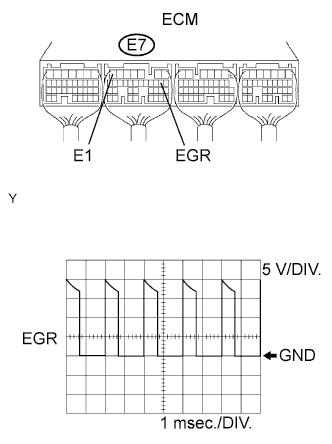 |
Disconnect the V1 E-VRV connector.
During idling, check the waveform of the ECM connector.
| Tester Connection | Specified Condition |
| E7-9 (EGR) - E7-7 (E1) | Correct waveform is as shown |
| Tool Setting | Condition |
| 5 V/DIV., 1 msec./DIV. | Idling with warm engine |
|
| ||||
| OK | |
|
| 8.CHECK OPERATION OF ELECTRIC VACUUM REGULATING VALVE FOR EGR |
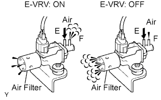 |
Disconnect the vacuum hoses from the E-VRV.
Connect the intelligent tester to the DLC3.
Turn the ignition switch ON and turn the intelligent tester ON.
Enter the following menus: Powertrain / Engine / Active Test / Control the EGR System.
Check the operation.
|
| ||||
| NG | |
|
| 9.INSPECT ELECTRIC VACUUM REGULATING VALVE FOR EGR (RESISTANCE) |
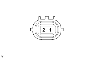 |
Disconnect the V1 E-VRV connector.
Measure the resistance of the E-VRV.
| Tester Connection | Condition | Specified Condition |
| 1 - 2 | 20°C (68°F) | 11 to 13 Ω |
|
| ||||
| OK | |
|
| 10.CHECK WIRE HARNESS (ELECTRIC VACUUM REGULATING VALVE FOR EGR - ECM) |
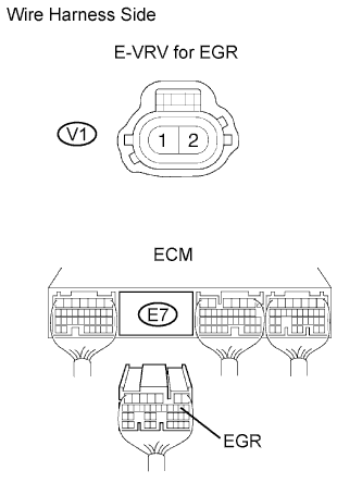 |
Disconnect the V1 E-VRV connector.
Disconnect the E7 ECM connector.
Measure the resistance of the wire harness side connectors.
| Tester Connection | Specified Condition |
| E7-9 (EGR) - V1-2 | Below 1 Ω |
| E7-9 (EGR) or V1-2 - Body ground | 10 kΩ or higher |
|
| ||||
| OK | |
|
| 11.CHECK WIRE HARNESS (ELECTRIC VACUUM REGULATING VALVE FOR EGR - INTEGRATION RELAY (MAIN RELAY)) |
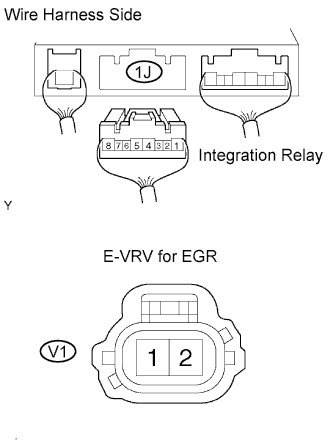 |
Remove the integration relay from the engine room junction block (Click here).
Disconnect the 1J integration relay connector.
Disconnect the V1 E-VRV connector.
Measure the resistance of the wire harness side connectors.
| Tester Connection | Specified Condition |
| 1J-5 - V1-1 | Below 1 Ω |
| 1J-5 or V1-1 - Body ground | 10 kΩ or higher |
|
| ||||
| OK | |
|
| 12.INSPECT EGR VALVE ASSEMBLY |
|
| ||||
| OK | ||
 | ||
| ||
| 1.CHECK CONNECTION OF VACUUM HOSE |
Check the connection of vacuum hose.
|
| ||||
| OK | |
|
| 2.CHECK VACUUM |
|
Using a 3-way connector, connect a vacuum gauge to the vacuum hose between the E-VRV for EGR and EGR valve.
Warm up the engine to above 80°C (176°F).
Check the vacuum at 1,500rpm.
| Vacuum | Proceed to |
| 0 kPa (0 mmHg, 0 in.Hg) | A |
| 0 kPa (0 mmHg, 0 in.Hg) to 28 kPa (210 mmHg, 8.3 in.Hg) | B |
| Above 28 kPa (210 mmHg, 8.3 in.Hg) | C |
|
| ||||
|
| ||||
| B | |
|
| 3.INSPECT VACUUM SWITCHING VALVE FOR EGR CUT |
|
Disconnect the V2 VSV connector.
Measure the resistance of the VSV.
| Tester Connection | Condition | Specified Condition |
| 1 - 2 | 20°C (68°F) | 37 to 44 Ω |
|
| ||||
| OK | |
|
| 4.INSPECT VACUUM SWITCHING VALVE FOR EGR CUT (OPERATION) |
|
| ||||
| OK | |
|
| 5.CHECK WIRE HARNESS (VACUUM SWITCHING VALVE FOR EGR CUT - ECM) |
|
Disconnect the V2 VSV connector.
Disconnect the E7 ECM connector.
Measure the resistance of the wire harness side connectors.
| Tester Connection | Specified Condition |
| E7-18 (EGRC) - V2-2 | Below 1 Ω |
| E7-18 (EGRC) or V2-2 - Body ground | 10 kΩ or higher |
|
| ||||
| OK | |
|
| 6.CHECK WIRE HARNESS (VACUUM SWITCHING VALVE FOR EGR CUT - INTEGRATION RELAY (MAIN RELAY)) |
|
Remove the integration relay from the engine room junction block (Click here).
Disconnect the 1J integration relay connector.
Disconnect the V2 VSV connector.
Measure the resistance of the wire harness side connectors.
| Tester Connection | Specified Condition |
| 1J-5 - V2-1 | Below 1 Ω |
| 1J-5 or V2-1 - Body ground | 10 kΩ or higher |
|
| ||||
| OK | |
|
| 7.CHECK ECM (EGR VOLTAGE) |
|
Disconnect the V1 E-VRV connector.
During idling, check the waveform of the ECM connector.
| Tester Connection | Specified Condition |
| E7-9 (EGR) - E7-7 (E1) | Correct waveform is as shown |
| Tool Setting | Condition |
| 5 V/DIV., 1 msec./DIV. | Idling with warm engine |
|
| ||||
| OK | |
|
| 8.INSPECT ELECTRIC VACUUM REGULATING VALVE FOR EGR (RESISTANCE) |
|
Disconnect the V1 E-VRV connector.
Measure the resistance of the E-VRV.
| Tester Connection | Condition | Specified Condition |
| 1 - 2 | 20°C (68°F) | 11 to 13 Ω |
|
| ||||
| OK | |
|
| 9.INSPECT ELECTRIC VACUUM REGULATING VALVE FOR EGR (OPERATION) |
|
| ||||
| OK | |
|
| 10.CHECK WIRE HARNESS (ELECTRIC VACUUM REGULATING VALVE FOR EGR - ECM) |
|
Disconnect the V1 E-VRV connector.
Disconnect the E7 ECM connector.
Measure the resistance of the wire harness side connectors.
| Tester Connection | Specified Condition |
| E7-9 (EGR) - V1-2 | Below 1 Ω |
| E7-9 (EGR) or V1-2 - Body ground | 10 kΩ or higher |
|
| ||||
| OK | |
|
| 11.CHECK WIRE HARNESS (ELECTRIC VACUUM REGULATING VALVE FOR EGR - INTEGRATION RELAY (MAIN RELAY)) |
|
Remove the integration relay from the engine room junction block (Click here).
Disconnect the 1J integration relay connector.
Disconnect the V1 E-VRV connector.
Measure the resistance of the wire harness side connectors.
| Tester Connection | Specified Condition |
| 1J-5 - V1-1 | Below 1 Ω |
| 1J-5 or V1-1 - Body ground | 10 kΩ or higher |
|
| ||||
| OK | |
|
| 12.INSPECT EGR VALVE ASSEMBLY |
|
| ||||
| OK | ||
| ||
| ||

