Home › ENGINE · 2KD-FTV › ENGINE CONTROL SYSTEM › ECD SYSTEM (w/o EGR Cooler)

DTC    P0400/71    Exhaust Gas Recirculation Flow

for Preparation Click here


DESCRIPTION

The EGR system recirculates exhaust gases, and adjusts the volume of the exhaust gases to the proper level depending on driving conditions. The recirculated gas mixes with the intake air, allowing the EGR system to slow down engine combustion and lower the combustion temperature. This helps reduce NOx emissions.
In order to increase circulation efficiency, the ECM adjusts the lift amount of the EGR valve and throttle valve.

DTC No.
DTC Detection Condition
Trouble Area
P0400/71
When either condition below is met:
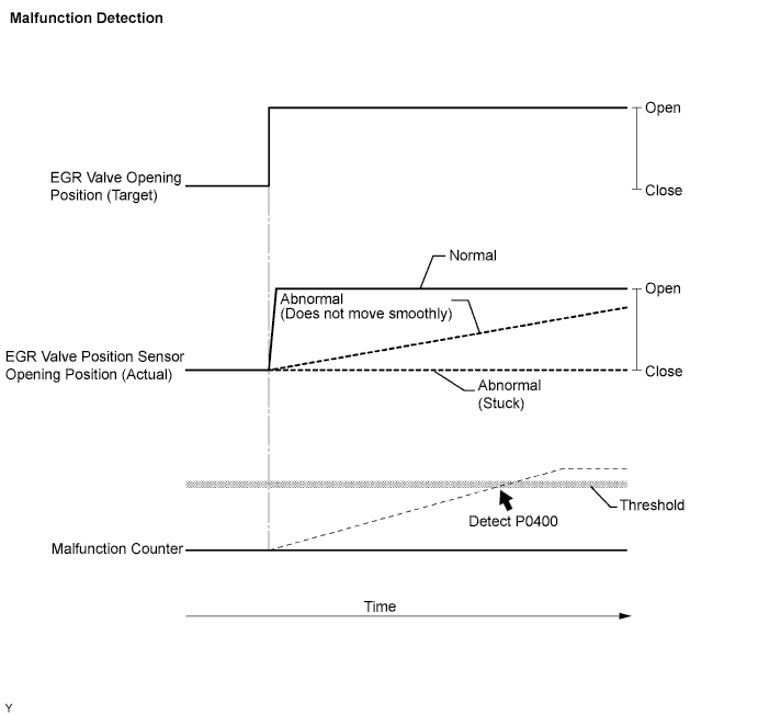
  1. Difference between target and actual position of EGR valve is 25% or more for 69 seconds or more
    (1 trip detection logic)
  1. EGR valve stuck
  2. EGR valve does not move smoothly
  3. Open or short in E-VRV for EGR circuit
  4. Open or short in EGR valve position sensor circuit
  5. EGR valve position sensor
  6. Vacuum pump
  7. Vacuum hose
  8. ECM

HINT:
DTC detection is not performed for 4 seconds after the brake switch is turned ON and OFF.


MONITOR DESCRIPTION

When the target and actual position of the EGR valve are different, the ECM interprets this as a malfunction of the EGR valve and illuminates the MIL.

A093020E05


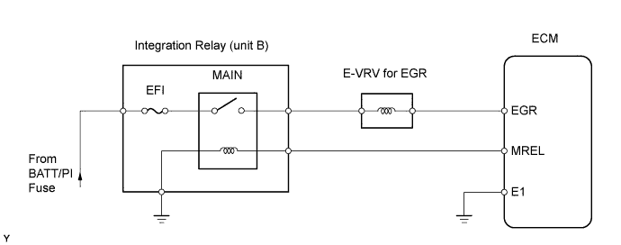
WIRING DIAGRAM


A119975E01


INSPECTION PROCEDURE

HINT:
  1. Read freeze frame data using the intelligent tester. Freeze frame data records the engine conditions when a malfunction is detected. When troubleshooting, freeze frame data can help determine if the vehicle was running or stopped, if the engine was warmed up or not, and other data from the time the malfunction occurred.
  2. After warming up the engine, DTC P0400/71 is set 1 second or more after quickly accelerating the engine from idling.

NOTICE:
If the ECM is replaced, the new ECM needs initialization (Click here).

1.CHECK OTHER DTC OUTPUT
  1. Connect the intelligent tester to the DLC3.

  1. Turn the ignition switch ON and turn the intelligent tester ON.

  1. Enter the following menus: Powertrain / Engine / DTC.

  1. Read DTCs.

    Result:
    Display (DTC output)
    Proceed to
    P0400/71 only
    A
    P0400/71 and P0405/96
    B
    P0400/71 and P0406/96
    B


B
GO TO RELEVANT DTC CHART
A


2.INSPECT VACUUM PUMP ASSEMBLY


NG
REPLACE VACUUM PUMP ASSEMBLY
OK


3.CHECK VACUUM HOSE
  1. Check the vacuum hoses of EGR system.


NG
REPLACE VACUUM HOSE
OK


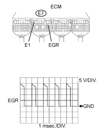
4.CHECK ECM (EGR VOLTAGE)
G034909E05
  1. While idling the engine, check the waveform of the ECM connector.

    OK:
    Tester Connection
    Specified Condition
    E7-9 (EGR) - E7-7 (E1)
    Correct waveform is shown

    Tool Setting
    Condition
    5 V/DIV., 1 msec./DIV.
    Idling with warm engine

    HINT:
    The waveform varies depending on the throttle valve operation.


NG
REPLACE ECM
OK


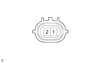
5.INSPECT ELECTRIC VACUUM REGULATING VALVE FOR EGR (RESISTANCE)
A093008E03
  1. Disconnect the V1 E-VRV connector.

  1. Measure the resistance of the E-VRV.

    Standard resistance:
    Tester Connection
    Condition
    Specified Condition
    1 - 2
    20°C (68°F)
    11 to 13 Ω


NG
REPLACE ELECTRIC VACUUM REGULATING VALVE FOR EGR
OK


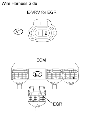
6.CHECK WIRE HARNESS (ELECTRIC VACUUM REGULATING VALVE FOR EGR - ECM)
A099854E06
  1. Disconnect the V1 E-VRV connector.

  1. Disconnect the E7 ECM connector.

  1. Measure the resistance of the wire harness side connectors.

    Standard resistance:
    Tester Connection
    Specified Condition
    E7-9 (EGR) - V1-2
    Below 1 Ω
    E7-9 (EGR) or V1-2 - Body ground
    10 kΩ or higher


NG
REPAIR OR REPLACE HARNESS AND CONNECTOR
OK


7.CHECK WIRE HARNESS (ELECTRIC VACUUM REGULATING VALVE FOR EGR - INTEGRATION RELAY (MAIN RELAY))
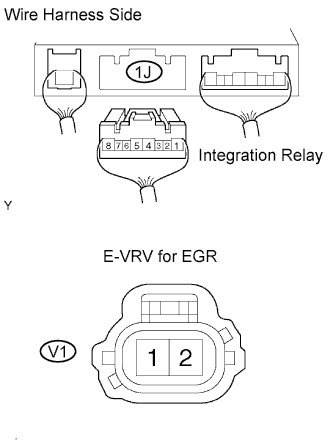
G034910E04
  1. Remove the integration relay from the engine room junction block (Click here).

  1. Disconnect the 1J integration relay connector.

  1. Disconnect the V1 E-VRV connector.

  1. Measure the resistance of the wire harness side connectors.

    Standard resistance:
    Tester Connection
    Specified Condition
    1J-5 - V1-1
    Below 1 Ω
    1J-5 or V1-1 - Body ground
    10 kΩ or higher


NG
REPAIR OR REPLACE HARNESS AND CONNECTOR
OK


8.INSPECT EGR VALVE ASSEMBLY


NG
REPLACE EGR VALVE ASSEMBLY
OK

REPLACE ECM