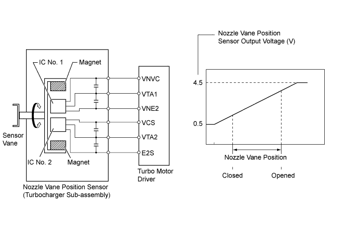
DTC P2563 Turbocharger/Supercharger Boost Control Position Sensor "A" Circuit Range/Performance |
DTC P2564 Turbocharger/Supercharger Boost Control Position Sensor "A" Circuit Low |
DTC P2565 Turbocharger/Supercharger Boost Control Position Sensor "A" Circuit High |
DTC P2588 Turbocharger/Supercharger Boost Control Position Sensor "B" Circuit Low |
DTC P2589 Turbocharger/Supercharger Boost Control Position Sensor "B" Circuit High |
| DTC No. | DTC Detection Condition | Trouble Area |
| P2563 | Difference between VTA1 and VTA2 0.8 V or more for 0.5 seconds or more (1 trip detection logic) | Nozzle vane position sensor (Turbocharger sub-assembly) |
| P2564 | VTA1 0.5 V or less for 0.5 seconds or more (1 trip detection logic) |
|
| P2565 | VTA1 4.5 V or more for 0.5 seconds or more (1 trip detection logic) |
|
| P2588 | VTA2 0.5 V or less for 0.5 seconds or more (1 trip detection logic) |
|
| P2589 | VTA2 4.5 V or more for 0.5 seconds or more (1 trip detection logic) |
|
| 1.CHECK OTHER DTC OUTPUT (IN ADDITION TO DTC P2563) |
Connect the intelligent tester to the DLC3.
Turn the ignition switch ON and turn the tester ON.
Enter the following menus: Powertrain / Engine and ECT / DTC.
Read the DTCs.
| Display (DTC Output) | Proceed to |
| P2563, P2564, P2565, P2588 and/or P2589 | A |
| P2563, P2564, P2565, P2588 and/or P2589, and other DTCs | B |
|
| ||||
| A | |
 |
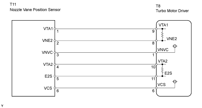
| 2.CHECK HARNESS AND CONNECTOR (NOZZLE VANE POSITION SENSOR - TURBO MOTOR DRIVER) |
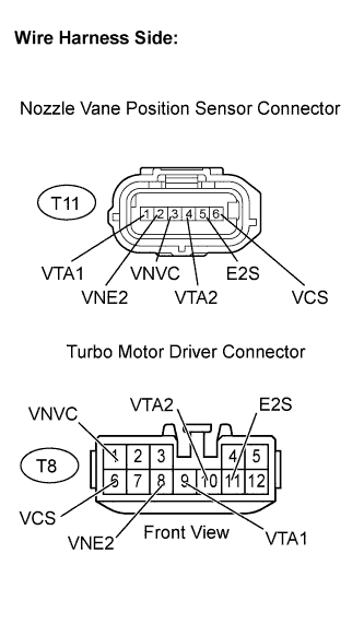 |
Disconnect the T11 nozzle vane position sensor connector.
Disconnect the T8 turbo motor driver connector.
Measure the resistance of the wire harness side connectors.
| Tester Connection | Specified Condition |
| VTA1 (T11-1) - VTA1 (T8-9) | Below 1 Ω |
| VNE2 (T11-2) - VNE2 (T8-8) | Below 1 Ω |
| VNVC (T11-3) - VNVC (T8-1) | Below 1 Ω |
| VTA2 (T11-4) - VTA2 (T8-10) | Below 1 Ω |
| E2S (T11-5) - E2S (T8-11) | Below 1 Ω |
| VCS (T11-6) - VCS (T8-6) | Below 1 Ω |
| Tester Connection | Specified Condition |
| VTA1 (T11-1) or VTA1 (T8-9) - Body ground | 10 kΩ or higher |
| VNE2 (T11-2) or VNE2 (T8-8) - Body ground | 10 kΩ or higher |
| VNVC (T11-3) or VNVC (T8-1) - Body ground | 10 kΩ or higher |
| VTA2 (T11-4) or VTA2 (T8-10) - Body ground | 10 kΩ or higher |
| E2S (T11-5) or E2S (T8-11) - Body ground | 10 kΩ or higher |
| VCS (T11-6) or VCS (T8-6) - Body ground | 10 kΩ or higher |
|
| ||||
| OK | |
|
| 3.INSPECT TURBO MOTOR DRIVER |
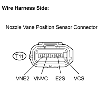 |
Disconnect the T11 nozzle vane position sensor connector.
Turn the ignition switch ON.
Measure the voltage between the terminals of the nozzle vane position sensor connector.
| Tester Connection | Specified Condition |
| VNVC (T11-3) - VNE2 (T11-2) | 4.5 to 5.5 V |
| VCS (T11-6) - E2S (T11-5) | 4.5 to 5.5 V |
|
| ||||
| OK | |
|
| 4.INSPECT NOZZLE VANE POSITION SENSOR |
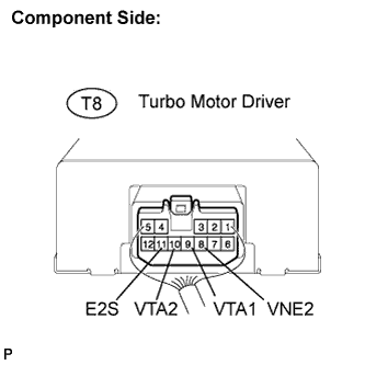 |
Turn the ignition switch ON.
Measure the voltage between the terminals of the turbo motor driver connector.
| Tester Connection | Specified Condition |
| VTA1 (T8-9) - VNE2 (T8-8) | 0.5 to 4.5 V |
| VTA2 (T8-10) - E2S (T8-11) | 0.5 to 4.5 V |
Check the difference between the voltage values.
|
| ||||
| OK | |
|
| 5.REPLACE TURBO MOTOR DRIVER |
| NEXT | |
|
| 6.CHECK WHETHER DTC OUTPUT RECURS (P2564, P2565, P2588 AND/OR P2589) |
Connect the intelligent tester to the DLC3.
Turn the ignition switch ON and turn the tester ON.
Clear DTCs (Click here).
Start the engine.
Perform the test drive.
Enter the following menus: Powertrain / Engine and ECT / DTC.
Read the DTCs.
| Display (DTC output) | Proceed to |
| P2563, P2564, P2565, P2588 and/or P2589 is output again | A |
| No output | B |
|
| ||||
| A | ||
 | ||
| ||
