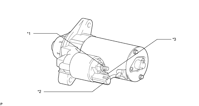
STARTER (for 2.2 kW Type) > INSPECTION |
| 1. INSPECT STARTER ASSEMBLY |
| *1 | Terminal 30 | *2 | Terminal 50 |
| *3 | Terminal C | - | - |
Perform pull-in test.
Remove the nut, and then disconnect the field coil core from terminal C.
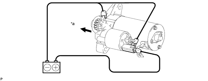
| *a | Operation | - | - |
Perform holding test.
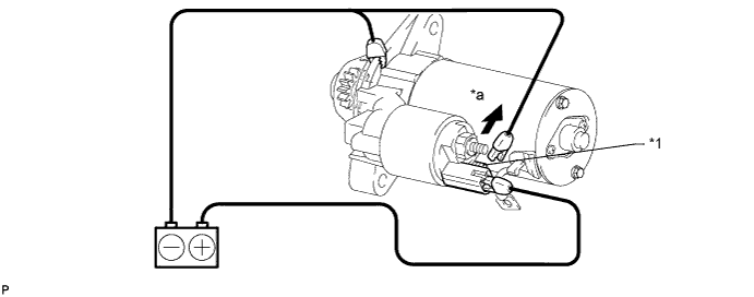
| *1 | Terminal C | - | - |
| *a | Disconnect | - | - |
Inspect clutch pinion gear return.
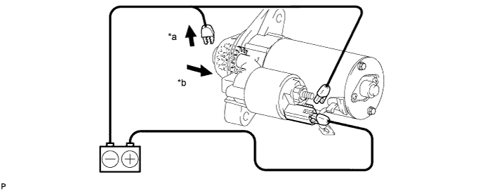
| *a | Disconnect | *b | Operation |
Perform operation test without load.
Connect the field coil lead wire to terminal C with the nut.
Mount the starter in a vise between aluminum plates.
Connect the battery and ammeter to the starter as shown in the illustration.
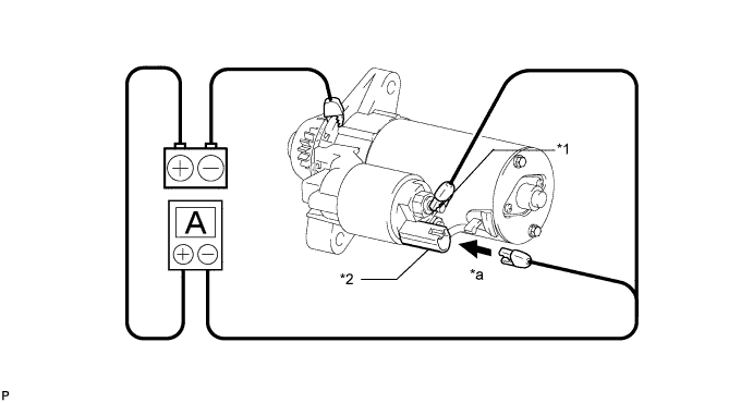
| *1 | Terminal 30 | *2 | Terminal 50 |
| *a | Connect | - | - |
| 2. INSPECT STARTER ARMATURE ASSEMBLY |
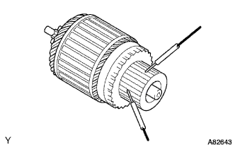 |
Measure the resistance.
Measure the resistance between the segments of the commutator.
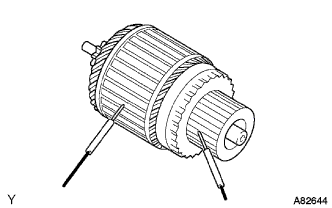 |
Measure the resistance between a segment of the commutator and armature coil core.
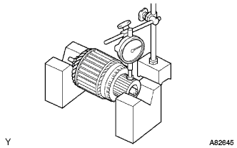 |
Inspect the commutator circle runout.
Place the commutator on V-blocks.
Using a dial indicator, measure the circle runout.
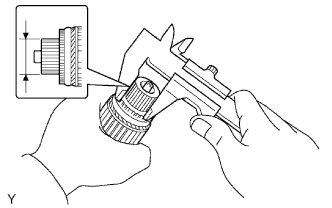 |
Using a vernier caliper, measure the commutator diameter.
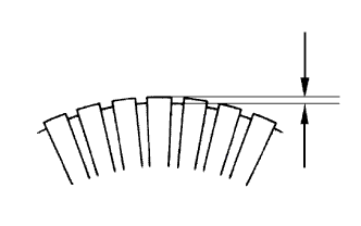 |
Using a vernier caliper, measure the undercut depth of the commutator.
| 3. INSPECT STARTER BRUSH HOLDER ASSEMBLY |
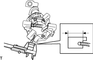 |
Using a vernier caliper, measure the brush length.
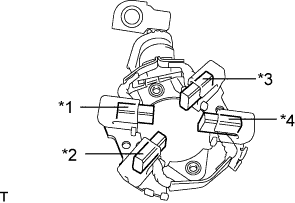 |
Check the brush holder.
Measure the resistance between the brushes.
| Tester Connection | Specified Condition |
| A - B | 10 kΩ or higher |
| A - C | 10 kΩ or higher |
| A - D | Below 1 Ω |
| B - C | Below 1 Ω |
| B - D | 10 kΩ or higher |
| C - D | 10 kΩ or higher |
| *1 | A |
| *2 | B |
| *3 | C |
| *4 | D |
| 4. INSPECT STARTER CLUTCH SUB-ASSEMBLY |
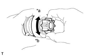 |
Rotate the pinion gear clockwise and check that it turns freely. Try to rotate the pinion gear counterclockwise and check that it locks.
| *a | Free |
| *b | Lock |
Turn the pinion gear by hand while applying inward force and check the movement of the bearing. If resistance is felt or the bearing sticks, replace the starter clutch sub-assembly.
| 5. INSPECT MAGNET STARTER SWITCH ASSEMBLY |
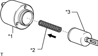 |
Check the plunger.
| *1 | Switch Body |
| *2 | Spring |
| *3 | Plunger |
Install the plunger and spring onto the switch body.
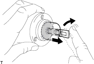 |
Push in the plunger and check that it returns quickly to its original position.
If the result is not as specified, replace the magnet starter switch assembly.
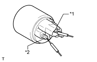 |
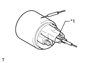
Check if the pull-in coil has an open circuit.
Measure the resistance between terminal 50 and terminal C.
| *1 | Terminal 50 |
| *2 | Terminal C |
 |
Check if the hold-in coil has an open circuit.
Measure the resistance between terminal 50 and the switch body.
| *1 | Terminal 50 |