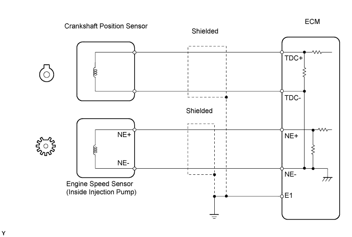
DTC 12 Crankshaft Position Sensor Circuit Malfunction |
| DTC No. | DTC Detection Condition | Trouble Area |
| 12 | No TDC signal to ECM at 400 rpm or more |
|
| 1.INSPECT CRANKSHAFT POSITION SENSOR |
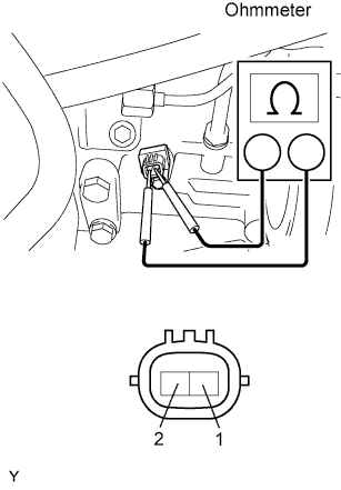 |
Check the crankshaft position sensor installation.
Disconnect the C5 crankshaft position sensor connector.
Measure the resistance of the crankshaft position sensor.
| Tester Connection | Condition | Specified Condition |
| 1 - 2 | Cold | 19 to 32 Ω |
| 1 - 2 | Hot | 24 to 37 Ω |
|
| ||||
| OK | |
 |
| 2.CHECK ECM (TDC, NE SIGNAL) |
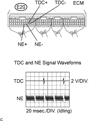 |
While cranking or idling, measure the waveform according to the value(s) in the table below.
| Tester Connection | Specified Condition |
| E20-17 (TDC+) - E20-16 (TDC-) | Correct waveform is as shown |
| E20-19 (NE+) - E20-18 (NE-) | Correct waveform is as shown |
| Tool Setting | Condition |
| 2 V/DIV., 20 msec./DIV. | During idling |
|
| ||||
| NG | |
|
| 3.CHECK HARNESS AND CONNECTOR (ECM - CRANKSHAFT POSITION SENSOR) |
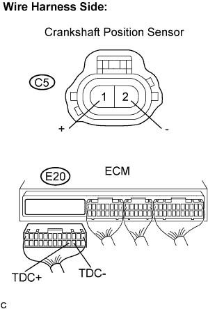 |
Disconnect the C5 crankshaft position sensor connector.
Disconnect the E20 ECM connector.
Measure the resistance of the wire harness side connectors.
| Tester Connection | Specified Condition |
| C5-1 (+) - E20-17 (TDC+) | Below 1 Ω |
| C5-2 (-) - E20-16 (TDC-) | Below 1 Ω |
| E20-17 (TDC+) - E20-16 (TDC-) | 10 kΩ or higher |
| C5-1 (+) or E20-17 (TDC+) - Body ground | 10 kΩ or higher |
| C5-2 (-) or E20-16 (TDC-) - Body ground | 10 kΩ or higher |
|
| ||||
| OK | ||
 | ||
| ||
