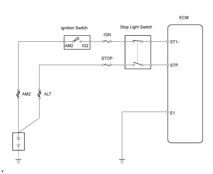
DTC 51 Stop Light Switch Circuit Malfunction |
| Signal | Brake pedal released | In transition | Brake pedal depressed |
| STP | OFF | ON | ON |
| ST1- | ON | ON | OFF |
| DTC No. | DTC Detection Condition | Trouble Area |
| 51 | When STP (without depressing the brake pedal) and ST1- (with the brake pedal depressed) signals continue for longer than 0.5 seconds with the ignition switch ON |
|
| 1.READ VALUE USING INTELLIGENT TESTER (STOP LIGHT SWITCH) |
Connect the intelligent tester to the DLC3.
Turn the ignition switch ON.
Enter the following menus: Powertrain / Engine and ECT / Data List / Stop Light SW.
| Brake Pedal | Display |
| Depressed | Stop Light SW ON |
| Repressed | Stop Light SW OFF |
|
| ||||
| NG | |
 |
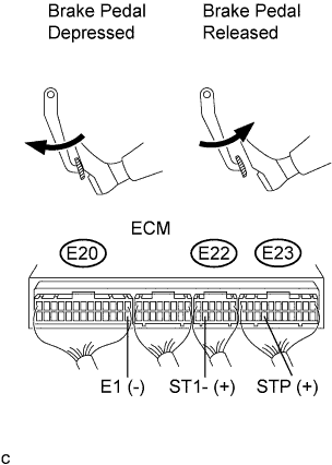
| 2.CHECK ECM (STP, ST1- VOLTAGE) |
 |
Turn the ignition switch ON.
Measure the voltage of the ECM connector.
| Tester Connection | Specified Condition |
| E23-19 (STP) - E20-14 (E1) | 9 to 14 V |
| E22-11 (ST1-) - E20-14 (E1) | Below 1.5 V |
| Tester Connection | Specified Condition |
| E23-19 (STP) - E20-14 (E1) | Below 1.5 V |
| E22-11 (ST1-) - E20-14 (E1) | 9 to 14 V |
|
| ||||
| NG | |
|
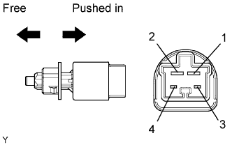
| 3.INSPECT STOP LIGHT SWITCH |
 |
Disconnect the stop light switch connector.
Measure the resistance of the sensor.
| Tester Connection | Switch Position | Specified Condition |
| 3 - 4 | Switch pin free | Below 1 Ω |
| 3 - 4 | Switch pin pushed in | 10 kΩ or higher |
| 1 - 2 | Switch pin free | 10 kΩ or higher |
| 1 - 2 | Switch pin pushed in | Below 1 Ω |
|
| ||||
| OK | |
|
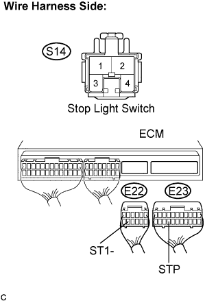
| 4.CHECK HARNESS AND CONNECTOR (ECM - STOP LIGHT SWITCH) |
 |
Disconnect the S14 stop light switch connector.
Disconnect the E22 and E23 ECM connectors.
Measure the resistance of the wire harness side connectors.
| Tester Connection | Specified Condition |
| S14-1 - E23-19 (STP) | Below 1 Ω |
| S14-4 - E22-11 (ST1-) | Below 1 Ω |
| S14-1 or E23-19 (STP) - Body ground | 10 kΩ or higher |
| S14-4 or E22-11 (ST1-) - Body ground | 10 kΩ or higher |
|
| ||||
| OK | ||
 | ||
| ||
| 1.CHECK STOP LIGHT (OPERATION) |
Check if the stop lights go on and off normally when the brake pedal is depressed and released.
|
| ||||
| OK | |
|
| 2.CHECK ECM (STP, ST1- VOLTAGE) |
|
Turn the ignition switch ON.
Measure the voltage of the ECM connector.
| Tester Connection | Specified Condition |
| E23-19 (STP) - E20-14 (E1) | 9 to 14 V |
| E22-11 (ST1-) - E20-14 (E1) | Below 1.5 V |
| Tester Connection | Specified Condition |
| E23-19 (STP) - E20-14 (E1) | Below 1.5 V |
| E22-11 (ST1-) - E20-14 (E1) | 9 to 14 V |
|
| ||||
| NG | |
|
| 3.INSPECT STOP LIGHT SWITCH |
|
Disconnect the stop light switch connector.
Measure the resistance of the sensor.
| Tester Connection | Switch Position | Specified Condition |
| 3 - 4 | Switch pin free | Below 1 Ω |
| 3 - 4 | Switch pin pushed in | 10 kΩ or higher |
| 1 - 2 | Switch pin free | 10 kΩ or higher |
| 1 - 2 | Switch pin pushed in | Below 1 Ω |
|
| ||||
| OK | |
|
| 4.CHECK HARNESS AND CONNECTOR (ECM - STOP LIGHT SWITCH) |
|
Disconnect the S14 stop light switch connector.
Disconnect the E22 and E23 ECM connectors.
Measure the resistance of the wire harness side connectors.
| Tester Connection | Specified Condition |
| S14-1 - E23-19 (STP) | Below 1 Ω |
| S14-4 - E22-11 (ST1-) | Below 1 Ω |
| S14-1 or E23-19 (STP) - Body ground | 10 kΩ or higher |
| S14-4 or E22-11 (ST1-) - Body ground | 10 kΩ or higher |
|
| ||||
| OK | ||
| ||
| ||
