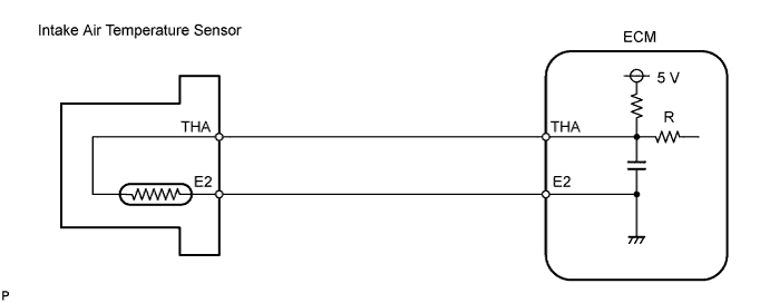
DTC 23 Air Temperature Circuit Malfunction |
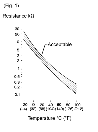
| DTC No. | DTC Detection Condition | Trouble Area |
| 23 | Open or short in intake air temperature sensor circuit for 0.5 sec. or more |
|
| 1.READ VALUE USING INTELLIGENT TESTER (INTAKE AIR TEMPERATURE) |
Connect the intelligent tester to the DLC3.
Turn the ignition switch ON.
Enter the following menus: Powertrain / Engine and ECT / Data List / Intake Air.
| Display | Proceed to |
| -40°C (-40°F) | A |
| 140°C (284°F) or more | B |
| The same as actual engine coolant temperature | C |
| Temperature Displayed | Malfunction |
| -40°C (-40°F) | Open circuit |
| 140°C (284°F) or more | Short circuit |
|
| ||||
|
| ||||
| A | |
 |
| 2.READ VALUE USING INTELLIGENT TESTER (CHECK FOR OPEN IN WIRE HARNESS) |
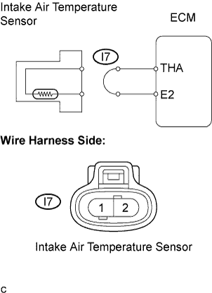 |
Disconnect the I7 intake air temperature sensor connector.
Connect terminals 1 and 2 of the intake air temperature sensor harness side connector.
Turn the ignition switch ON.
Read the temperature value on the intelligent tester.
|
| ||||
| NG | |
|
| 3.READ VALUE USING INTELLIGENT TESTER (CHECK FOR OPEN IN ECM) |
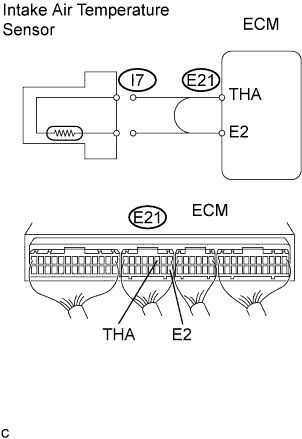 |
Connect between terminals THA and E2 of the ECM connector.
Turn the ignition switch ON.
Read the temperature value on the intelligent tester.
|
| ||||
| OK | ||
 | ||
| ||
| 4.READ VALUE USING INTELLIGENT TESTER (CHECK FOR SHORT IN WIRE HARNESS) |
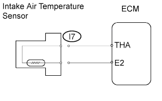 |
Disconnect the I7 intake air temperature sensor connector.
Turn the ignition switch ON.
Read the temperature value on the intelligent tester.
|
| ||||
| NG | |
|
| 5.READ VALUE USING INTELLIGENT TESTER (CHECK FOR SHORT IN ECM) |
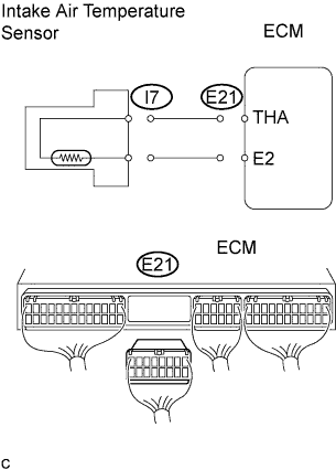 |
Disconnect the E21 ECM connector.
Turn the ignition switch ON.
Read the temperature value on the intelligent tester.
|
| ||||
| OK | ||
| ||
| ||
| 1.CHECK ECM |
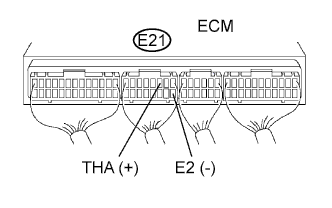 |
Turn the ignition switch ON.
Measure the voltage of the ECM connector.
| Tester Connection | Condition | Specified Condition |
| E21-3 (THA) - E21-9 (E2) | 20°C (68°F) | 0.2 to 3.8 V |
| E21-3 (THA) - E21-9 (E2) | 80°C (176°F) | 0.1 to 1.5 V |
|
| ||||
| NG | |
|
| 2.INSPECT INTAKE AIR TEMPERATURE SENSOR |
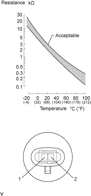 |
Measure the resistance of the intake air temperature sensor.
|
| ||||
| OK | |
|
| 3.CHECK HARNESS AND CONNECTOR (ECM - INTAKE AIR TEMPERATURE SENSOR) |
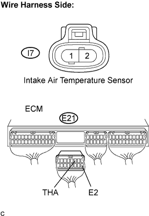 |
Disconnect the I7 intake air temperature sensor connector.
Disconnect the E21 ECM connector.
Measure the resistance of the wire harness side connectors.
| Tester Connection | Specified Condition |
| I7-2 - E21-3 (THA) | Below 1 Ω |
| I7-1 - E21-9 (E2) | Below 1 Ω |
| E21-3 (THA) - E21-9 (E2) | 10 kΩ or higher |
|
| ||||
| OK | ||
| ||
| ||

