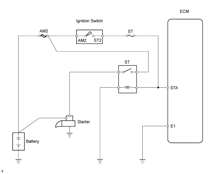
ECD SYSTEM > Starter Signal Circuit |
| 1.READ VALUE USING INTELLIGENT TESTER (STA SIGNAL) |
Connect the intelligent tester to the DLC3.
Turn the ignition switch ON and turn the tester ON.
Enter the following menus: Powertrain / Engine and ECT / Data List / Starter Signal.
Read the STA signal on the intelligent tester while the starter operates.
| Ignition Switch Position | STA Signal |
| LOCK, ACC, ON | OFF |
| START | ON |
|
| ||||
| NG | |
 |
| 2.INSPECT FUSE (ST) |
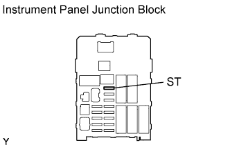 |
Remove the ST fuse from the instrument panel junction block.
Measure the resistance of the fuse.
| Tester Connection | Specified Condition |
| ST fuse | Below 1 Ω |
|
| ||||
| OK | |
|
| 3.CHECK HARNESS AND CONNECTOR (IGNITION SWITCH - ST FUSE, ST FUSE - ECM) |
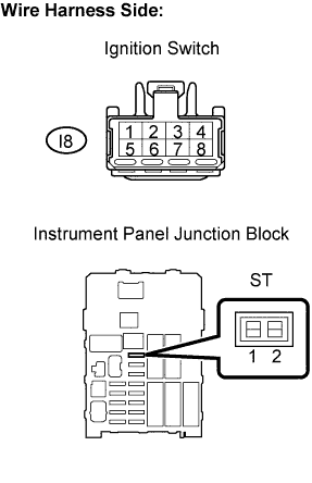 |
Check the wire harness between the ignition switch and ST fuse.
Disconnect the I8 ignition switch connector.
Remove the ST fuse from the instrument panel junction block.
Measure the resistance of the wire harness side connectors.
| Tester Connection | Specified Condition |
| I8-7 (ST2) - Instrument panel junction block ST fuse terminal 1 | Below 1 Ω |
| I8-7 (ST2) or instrument panel junction block ST fuse terminal 1 - Body ground | 10 kΩ or higher |
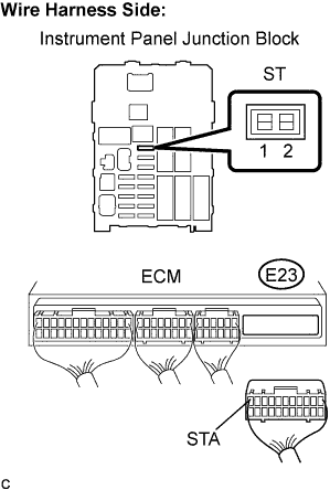 |
Check the wire harness between the ST fuse and ECM.
Remove the ST fuse from the instrument panel junction block.
Disconnect the E23 ECM connector.
Measure the resistance of the wire harness side connectors.
| Tester Connection | Specified Condition |
| Instrument panel junction block ST fuse terminal 2 - E23-11 (STA) | Below 1 Ω |
| Instrument panel junction block ST fuse terminal 2 or E23-11 (STA) - Body ground | 10 kΩ or higher |
|
| ||||
| OK | ||
 | ||
| ||
| 1.CHECK ECM (STA VOLTAGE) |
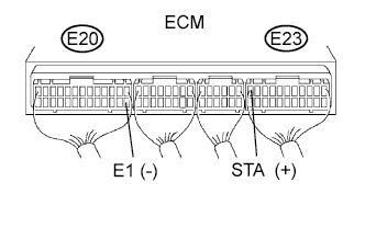 |
Turn the ignition switch ON.
Measure the voltage of the ECM connector.
| Tester Connection | Condition | Specified Condition |
| E23-11 (STA) - E20-14 (E1) | Cranking | 6 V or more |
|
| ||||
| NG | |
|
| 2.INSPECT FUSE (ST) |
|
Remove the ST fuse from the instrument panel junction block.
Measure the resistance of the ST fuse.
| Tester Connection | Specified Condition |
| ST fuse | Below 1 Ω |
|
| ||||
| OK | |
|
| 3.CHECK HARNESS AND CONNECTOR (IGNITION SWITCH - ST FUSE, ST FUSE - ECM) |
|
Check the wire harness between the ignition switch and ST fuse.
Disconnect the I8 ignition switch connector.
Remove the ST fuse from the instrument panel junction block.
Measure the resistance of the wire harness side connectors.
| Tester Connection | Specified Condition |
| I8-7 (ST2) - Instrument panel junction block ST fuse terminal 1 | Below 1 Ω |
| I8-7 (ST2) or instrument panel junction block ST fuse terminal 1 - Body ground | 10 kΩ or higher |
|
Check the wire harness between the ST fuse and ECM.
Remove the ST fuse from the instrument panel junction block.
Disconnect the E23 ECM connector.
Measure the resistance of the wire harness side connectors.
| Tester Connection | Specified Condition |
| Instrument panel junction block ST fuse terminal 2 - E23-11 (STA) | Below 1 Ω |
| Instrument panel junction block ST fuse terminal 2 or E23-11 (STA) - Body ground | 10 kΩ or higher |
|
| ||||
| OK | ||
| ||
| ||
