FRONT DRIVE SHAFT ASSEMBLY > REASSEMBLY |
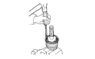
| 1. INSTALL FRONT AXLE HUB DUST SEAL |
|
Using a screwdriver and hammer, tap in a new dust seal.
| 2. INSTALL FRONT DRIVE SHAFT DUST COVER |
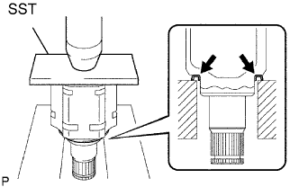 |
Using SST and a press, press in a new dust cover.
| 3. INSTALL HOLE SNAP RING |
Install a new snap ring.
| 4. INSTALL OUTBOARD JOINT BOOT |
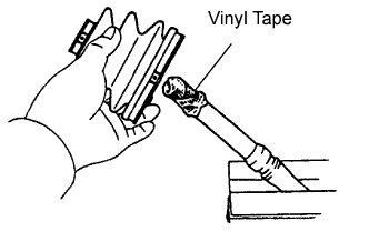 |
Temporarily install a new outboard joint boot (with 2 boot clamps) to the drive shaft.
Pack the outboard joint and boot with grease from a boot kit.
| 5. INSTALL FRONT AXLE OUTBOARD JOINT BOOT CLAMP |
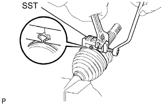 |
Mount the drive shaft in a soft vise.
Secure a new outboard joint large boot clamp onto the boot.
Place SST onto the clamp.
Tighten SST so that the boot clamp is pinched as shown in the illustration.
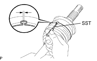 |
Using SST, adjust the clearance of the clamp.
For the outboard joint small boot clamp, use the same procedures described above.
| 6. INSTALL INBOARD JOINT BOOT |
Install a new inboard joint boot to the outboard joint shaft.
| 7. INSTALL INBOARD JOINT |
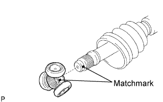 |
Align the matchmarks of the tripod and outboard joint.
Using a brass bar and hammer, tap the tripod onto the outboard joint.
Using a snap ring expander, install a new snap ring.
Pack the inboard joint and boot with grease from a boot kit.
Align the matchmarks of the inboard joint and outboard joint.
Install the inboard joint to the outboard joint.
| 8. INSTALL FRONT AXLE INBOARD JOINT BOOT CLAMP |
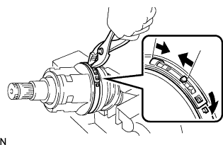 |
Using pliers, squeeze together the hooks of a new large clamp and install the large clamp.
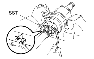 |
Secure a new small boot clamp onto the boot.
Place SST onto the small boot clamp.
Tighten SST so that the small boot clamp is pinched as shown in the illustration.
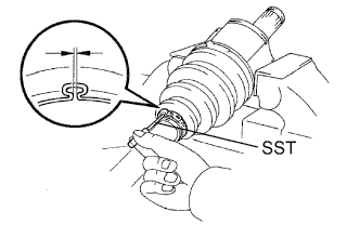 |
Using SST, adjust the clearance of the small boot clamp.
| 9. INSPECT FRONT DRIVE SHAFT ASSEMBLY LH |
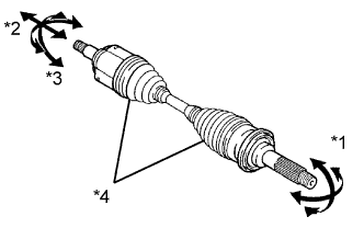 |
*1: Check that there is no excessive play in the outboard joint.
*2: Check that the inboard joint slides smoothly in the thrust direction.
*3: Check that there is no excessive play in the radial direction of the inboard joint.
*4: Check the boots for damage.